
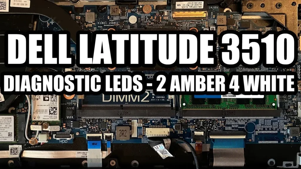
How to Fix Dell Blinking 2 Amber 4 White
A diagnostic LED code of 2 Amber, 4 White on a Dell laptop or desktop indicates a Memory / RAM failure. During the Power-On Self-Test (POST), the system detects that physical memory modules are present in the slots, but the BIOS/UEFI cannot successfully initialize, configure, or pass read/write training checks across the memory bus.
While this code can indicate a physically defective RAM stick, it is frequently caused by surface oxidation on the module’s gold contact fingers, dust contamination inside the SODIMM/DIMM slot, an uneven seated angle, or a stalled memory-training state caused by stale Real-Time Clock (RTC) / CMOS tables.
Quick Diagnostic Matrix
| Context / Symptom | Likely Root Cause | Diagnostic Action | Recommended Fix |
| Blink code started suddenly after sleep, transit, or a minor bump | SODIMM module unlatched or contact fingers shifted out of alignment | Open base cover / chassis | Remove and reseat the RAM modules firmly until the retaining clips snap in place. |
| Error appeared after installing a new or upgraded RAM stick | Spec mismatch (voltage, density, rank) or BIOS requires initial memory training | Spec check (JEDEC vs. XMP) | Install JEDEC-standard RAM matching factory clock/timings; allow up to 3 minutes for memory training. |
| Blinks 2 Amber, 4 White; fans spin, display remains black | Stale CMOS/NVRAM state tables blocking memory bus configuration | Power button / RTC pins | Execute a 30-second RTC / Flea-Power Reset to flush NVRAM registers. |
| Code occurs with Stick A, but clears when using Stick B | Individual memory cell defect, bad SPD chip, or cracked SMD component | Single-stick isolation test | Replace the defective RAM module. |
| Laptops with soldered memory (XPS 13, Precision thin models) | Failed LPDDR BGA solder balls or blown memory power rail regulator | Physical board inspection | Requires component-level BGA rework or a complete motherboard replacement. |
1. Execute an RTC (Real-Time Clock) & Flea-Power Reset
Stale memory configurations in the non-volatile random-access memory (NVRAM) can cause the motherboard’s Embedded Controller (EC) and BIOS to lock up during initial memory timings configuration. Modern Dell systems feature a hardware-level RTC Reset function that clears low-level power tables and forces the BIOS to rebuild its memory map without needing to open the chassis.
[Dell Hardware RTC Reset Procedure]
 1. Shut down laptop completely & connect the original Dell AC adapter.
 2. Press and HOLD the physical [Power Button] for 30 to 35 continuous seconds.
 3. The Power LED will blink three times ──► Release the button.
 4. System automatically cycles power 2–3 times (Memory Training Phase).
 5. Wait up to 3 minutes for Dell logo to appear on screen.
- Power off the system completely and plug in the authentic Dell AC power adapter.
- Press and hold the Power button for a full 30 to 35 seconds.
- What happens: The system may power on, turn off, and flash its front status LED. Do not let go until the power light flashes three times rapidly (around the 30-second mark), signaling that the RTC reset routine has executed.
- Release the Power button.
- The system will now initiate a cold boot sequence. Allow the system to sit undisturbed for up to 3 minutes. During this phase, the system will cycle power several times and perform initial memory training. Once complete, the 2 Amber, 4 White LED code should clear, and the Dell splash logo will appear.
2. Reseat and Clean the RAM Modules & Slots
Fine surface oxidation on the gold contact fingers or microscopic fibers wedged into the spring-loaded slot pins will degrade the high-speed differential signal traces, causing the memory controller to abort the link initialization.
[SODIMM Laptop Memory Slot Profile]
 ┌────────────────────────────────────────────────────────┐
 │ Motherboard PCB                                        │
 │   ┌────────────────────────────────────────────────┐   │
 │   │ Memory Slot Socket (Retaining Spring Arms)     │   │
 │   │ ┌────────────────────────────────────────────┐ │   │
 │   │ │ RAM Module (Inserted at 30-Degree Angle)   │ │   │ <── Push down firmly until
 │   │ └─────────────────────┬──────────────────────┘ │   │     metal clips snap into
 │   └───────────────────────┼────────────────────────┘   │     the side notches!
 └───────────────────────────┴────────────────────────────┘
- Safety Preparation:
- Disconnect the AC adapter.
- Remove the bottom base cover (laptops) or side access panel (desktops).
- Crucial: Disconnect the main battery cable from the motherboard before touching any internal components. Press the power button for 5 seconds to drain remaining motherboard capacitance.
- Extract the RAM Modules:
- Gently push the metal retaining arms on each side of the memory socket outward away from the module.
- The stick will pop up at roughly a $30^circ$ angle. Slide it straight out of the socket.
- Clean the Contact Fingers:
- Use a soft, clean pencil eraser across the row of gold contacts on both sides of the RAM stick to strip away microscopic oxidation films. Brush away any eraser shavings.
- Wipe the contacts with a lint-free swab lightly dampened with 99% isopropyl alcohol (IPA) and allow it to dry completely.
- Clean the Sockets:
- Direct short bursts of compressed air into the RAM socket slots to blow out accumulated dust, pet hair, or lint. Do not insert foreign objects into the delicate slot pins.
- Reinstall with Proper Angle and Pressure:
- Align the notch on the memory module with the key in the socket slot.
- Insert the card firmly at a $30^circ$ angle until the gold pins are almost entirely hidden inside the connector.
- Press down evenly on the outer corners of the module until the metal side clips snap into the side notches with an audible click.
3. Isolate the Defective Stick or Socket (Cross-Testing)
If reseating both modules does not resolve the issue, determine whether the failure is an individual bad RAM stick or a damaged motherboard slot/channel.
[Single-Stick Isolation Diagnostic Matrix]
            ┌───────────────────┬───────────────────┐
            │   TEST CONFIG A   │   TEST CONFIG B   │
            ├───────────────────┼───────────────────┤
  Slot 1    │   [ Stick 1 ]     │      [ EMPTY ]    │
  Slot 2    │     [ EMPTY ]     │    [ Stick 1 ]    │
            └─────────┬─────────┴─────────┬─────────┘
                      ▼                   ▼
           (Repeat identical test sequence using Stick 2)
- Test Stick 1 Alone in Slot 1:
- Remove Stick 2 completely and set it aside.
- Install Stick 1 into Slot 1 (usually labeled
DIMM Aor the slot closest to the motherboard board surface on stacked laptop designs). - Power on the system. If it boots cleanly, Stick 1 and Slot 1 are functional.
- Test Stick 1 Alone in Slot 2:
- Move Stick 1 to Slot 2 (
DIMM B). - Power on the system. If the system fails with 2 Amber, 4 White, Slot 2 on the motherboard has suffered a trace fracture or slot pin failure.
- Test Stick 2 Alone in Slot 1:
- Remove Stick 1 and install Stick 2 into Slot 1.
- If the system fails to boot and produces the 2 Amber, 4 White blink code in a known-good slot, Stick 2 is defective and must be replaced.
4. Verify RAM Compatibility & Specifications
If this error occurred immediately after installing new aftermarket RAM, the installed modules likely do not match Dell’s strict JEDEC firmware tables.
- Operating Voltage: Verify whether your platform requires standard DDR4 ($1.2text{V}$), DDR3L ($1.35text{V}$ vs older $1.5text{V}$ DDR3), or DDR5 ($1.1text{V}$). Installing standard voltage RAM in a low-voltage circuit trips the memory rail regulator.
- JEDEC Profiles vs. XMP/EXPO: Most Dell commercial and mainstream BIOS chips (OptiPlex, Latitude, Inspiron) do not support Intel XMP or AMD EXPO memory profiles. Aftermarket “gaming” RAM modules that require an active XMP profile to hit their rated timings will default to an uncalibrated JEDEC baseline or fail to train, locking the board at 2 Amber, 4 White. Use certified JEDEC-compliant standard memory (e.g., Crucial, Micron, Samsung, SK Hynix).
- Dual-Rank vs. Single-Rank Limits: Select thin-and-light models cannot address high-density dual-rank ($2text{Rx}8$) memory or modules utilizing high-density $16text{Gb}$ DRAM dies on legacy chipsets. Check your service manual for maximum per-slot density limits.
5. Non-Removable / Soldered RAM (LPDDR4x / LPDDR5)
Many modern ultra-thin Dell laptops (such as the Dell XPS 13 series, Latitude 7000/9000 ultra-portables, and select Inspiron 2-in-1s) do not have physical RAM slots. Instead, Low-Power DDR (LPDDR) chips are soldered directly to the motherboard substrate surrounding the CPU.
[Motherboard Soldered Architecture]
 ┌────────────────────────────────────────────────────────┐
 │ Motherboard                                            │
 │   ┌─────────────────┐       ┌──────────────────────┐   │
 │   │ Intel / AMD CPU │ <═══> │ Soldered LPDDR BGA   │   │ <── Ball Grid Array
 │   │ Package         │       │ Memory Chips         │   │     Micro-Crack Fault
 │   └─────────────────┘       └──────────────────────┘   │
 └────────────────────────────────────────────────────────┘
If a system with fully soldered memory displays the 2 Amber, 4 White code:
- Complete the 30-second RTC Reset detailed in Section 1 twice.
- Disconnect the main battery, plug in the AC adapter, and allow the system to attempt auto-recovery.
- If the code persists on a board with soldered memory, the failure is hardware-level:
- Thermal Shock / Drop Impact: Physical drops or repeated thermal expansion cycles can crack the micro-solder balls under the BGA memory chips, breaking contact with the address/data buses.
- Power Rail Failure: The buck regulator IC supplying the $1.1text{V} / 0.6text{V}$ memory power plane ($V_{DDQ} / V_{DD2}$) has shorted or failed to generate the Power Good ($PGOOD$) signal to the Embedded Controller.
- Resolution: Soldered memory cannot be serviced without an SMD/BGA rework station. The entire motherboard must be repaired by a micro-soldering technician or replaced under warranty.
6. BIOS Corruption Recovery
Occasionally, a failed or interrupted background Windows UEFI firmware update will corrupt the system BIOS block responsible for memory bus timings, causing the system to misidentify installed memory as defective.
[Dell BIOS Recovery from Hard Drive]
 1. Power off the system completely.
 2. Disconnect the AC power adapter.
 3. Press and HOLD the [Ctrl + Esc] keys on the keyboard.
 4. While holding [Ctrl + Esc], plug the AC adapter into the system.
 5. Release [Ctrl + Esc] when the keyboard backlight / Power LED lights up.
 6. The BIOS Recovery Screen will display ──► Select "Recover BIOS" ──► Press Enter.
- Unplug the AC adapter.
- Press and hold down
Ctrl + Escon the keyboard. - While continuing to hold both keys, connect the AC power adapter to the laptop or desktop.
- If the recovery handshake succeeds, the system will bypass the standard POST check, initialize basic display output, and load the BIOS Recovery 2 / 3 utility.
- Select Recover BIOS and press Enter to re-flash the primary UEFI block from the protected on-disk recovery partition.
If the 2 Amber, 4 White error persists across all individual memory sticks in all slots after performing an RTC reset and cleaning all contacts, the fault has bypassed the RAM modules themselves. This indicates that either the secondary $V_{DD}$ memory power rail on the motherboard has suffered an open circuit, or the processor’s internal Integrated Memory Controller (IMC) has experienced silicon degradation, requiring a replacement of the processor (on desktop sockets) or the main motherboard assembly.