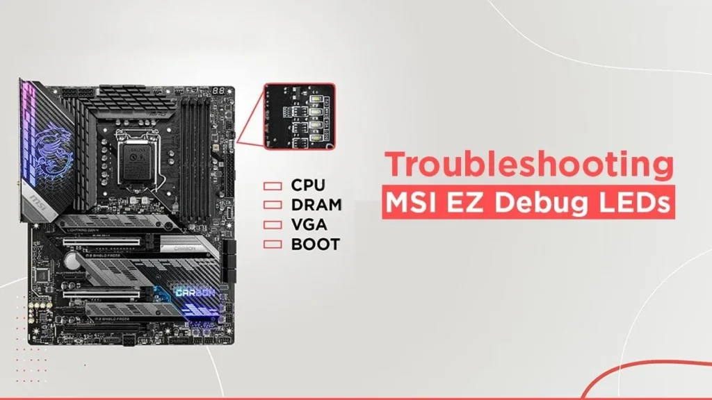
A solid red CPU light on the MSI EZ Debug LED cluster indicates that the motherboard cannot detect, initialize, or communicate with the processor during the Power-On Self-Test (POST). This halts the boot cycle before the board can check memory (DRAM), graphics (VGA), or the boot drive.
While it points to the CPU, actual processor failure is uncommon. In most cases, the red LED is caused by unseated power connectors, outdated BIOS microcode, uneven cooler mounting pressure, bent socket pins, or corrupted CMOS tables.
Quick Diagnostic Matrix
| Trigger / Context | Likely Root Cause | Diagnostic Action | Recommended Fix |
| New build or recently upgraded CPU | BIOS does not recognize newer processor generation | Check motherboard box / BIOS version | Flash latest BIOS via MSI Flash BIOS Button (no CPU/RAM required). |
| Fans spin at 100%, instantaneous solid red CPU light | Missing or incorrectly plugged EPS12V CPU power cable | Inspect top-left 8-pin CPU_PWR1 header | Connect dedicated 4+4 pin CPU/EPS cable; do NOT use a 6+2 PCIe GPU cable. |
| Light stays on after changing settings or unexpected crash | Corrupted CMOS register tables or power surge latch | JBAT1 jumper / CR2032 battery | Short JBAT1 pins for 10 seconds and perform cold flea-power drain. |
| Red CPU light, occasionally blinks or shifts to DRAM | Single-channel memory initialization failure or overtight cooler | Single RAM stick in slot A2 | Back off cooler screws by half a turn; test single memory stick in slot 2. |
| Red light remains after BIOS flash and power checks | Bent socket pins (LGA/AM5) or damaged CPU contacts (AM4) | Direct light inspection of socket | Inspect socket array for bent pins; reseat CPU with light, even mounting. |
Electrical & Socket Safety
Always turn off the power supply rocker switch (O) and disconnect the AC power cord from the wall before removing or reseating cables, RAM, or the CPU. Never force a power connector; forcing a PCIe cable into a CPU EPS header causes direct power rail shorts.
1. Verify CPU Power Connections (EPS12V): 2 min – Essential Check. Inspect the CPU_PWR1 (and CPU_PWR2 if present) connector located at the top-left edge of the motherboard.
Ensure the 8-pin (or 4+4 pin) cable is firmly latched into the socket.
Confirm you are using a cable clearly stamped CPU or EPS, not PCI-E (PCIe cables have different pinouts and keying).
If your power supply is modular, ensure the cable is firmly locked into the PSU’s designated CPU port.
Verification: The locking clip on the 8-pin connector audibly clicks over the header tab with no visible gap.
2. Clear CMOS & Perform Flea-Power Drain: 5 min – Clears register lockups. Reset the motherboard’s non-volatile settings to factory defaults.
Turn off the PSU switch and unplug the AC power cable from the wall.
Locate the two-pin JBAT1 header (usually near the bottom-right or adjacent to the coin-cell battery). Short the two pins together for 10–15 seconds using a flathead screwdriver or jumper cap.
Remove the CR2032 coin-cell battery for 5 minutes.
While unplugged, press and hold your PC case’s physical power button for 30 seconds to drain remaining capacitor energy.
Reinstall the battery, reconnect AC power, and turn the PC on.
Verification: The board reboots and may take 30–60 seconds for memory training before the red CPU light clears.
3. Update BIOS via MSI Flash BIOS Button: 10 min – Fixes CPU compatibility. If pairing a newer CPU with a motherboard manufactured earlier (e.g., Ryzen 5000 on B450/B550, Ryzen 7000/9000 on B650/X670, or Intel 13th/14th Gen on B660/Z690), the board will not POST without updated microcode.
On a working computer, download the latest stable BIOS for your exact motherboard model from MSI’s official support site.
Extract the downloaded ZIP file and rename the actual BIOS file (e.g., E7C91AMS.xxx) to MSI.ROM.
Format a USB 2.0 flash drive (32 GB or smaller) to FAT32 (using MBR partition style). Copy MSI.ROM directly to the root of the drive.
With the target PC powered off (PSU turned on so standby lights are active), insert the USB drive into the dedicated Flash BIOS Port outlined on the rear I/O shield.
Press the physical Flash BIOS Button on the rear I/O panel.
The LED next to the button will start blinking slowly, then flash rapidly for 5 to 8 minutes as the firmware writes to the board, after which the system will reboot.
Verification: The flashing stops and the motherboard reboots automatically. If the LED stays solid red or blinks only a few times and stops, the USB drive format or file name was not recognized.
4. Loosen Cooler Mounting Tension & Test Single RAM Stick: 5 min. Excessive or uneven cooler pressure flexes the motherboard PCB, lifting microscopic pins off the CPU pads and breaking communication with the Integrated Memory Controller (IMC).
Loosen each screw on the CPU cooler bracket by half a turn to one full turn.
Remove all RAM modules except for one single stick in slot A2 (the second slot outward from the CPU).
Power on the system.
Verification: The red CPU light turns off, or briefly turns red and then transitions to DRAM/VGA during normal POST initialization.
5. Inspect CPU Socket for Bent Pins & Foreign Debris: 15 min – Hardware check. If the red LED persists, remove the cooler and unlatch the CPU retention bracket.
Gently lift the CPU straight out of the socket.
Use a bright light and a smartphone camera with macro zoom to inspect the socket pin array (for Intel LGA or AMD AM5) or the underside of the processor (for AMD AM4 PGA).
Look for bent pins, pins pushed out of line, or thermal paste smeared across the gold contact pads/holes.
Reseat the CPU strictly aligning the golden triangle marker on the CPU corner with the triangle on the motherboard socket. Lock the retention arm.
Verification: All pins reflect light in a uniform grid pattern with no dark spots or misaligned angles across the array.
Out-of-Case Breadboard Test (Eliminating Case Shorts)
If the red CPU light persists after completing the steps above:
Remove the motherboard from the computer case to rule out an electrical short caused by an extra metal standoff or touching the chassis frame.
Place the board on its cardboard packaging box (never on the static bag, which has a conductive surface).
Connect only the 24-pin ATX power cable, the 8-pin CPU power cable, the CPU with cooler plugged into CPU_FAN1, and one stick of RAM in slot A2.
Disconnect all front-panel case wires, USB headers, audio headers, and SATA/M.2 drives.
Power on by shorting the two JFP1 power switch pins momentarily with a flathead screwdriver.
If the board still locks on the solid red CPU light on a bare test bench with a verified compatible BIOS and correct power cables, the fault is isolated to a physical component failure: either the motherboard’s primary Voltage Regulator Module (VRM) cannot deliver stable $V_{CORE}$ power, or the processor has suffered internal electrical damage. Testing with a known-working donor CPU or testing the CPU in a secondary compatible board will identify which component requires warranty replacement.