
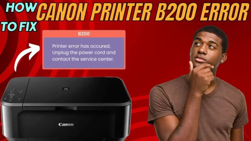
How to Fix Canon Service Code B200
Canon service code B200 is an unrecoverable hardware exception triggered when the mainboard ASIC detects an abnormal voltage or current condition on the printhead drive power rail ($VH$) or an uncontrolled thermal spike across the thermal inkjet micro-resistor array. Because Canon FINE printheads use thermal vaporization to eject ink, they rely on constant fluid flow to cool the heating elements; dry firing empty nozzles, conductive ink bridging rear electrical contacts, or internal silicon breakdown causes the power supply unit (PSU) to cut secondary voltage rails to protect the logic board from thermal destruction.
Quick Diagnostic Matrix
| Symptom | Root Cause | Inspection Point / Tool | Recommended Fix |
| B200 trips immediately upon power-on before carriage moves | Direct short circuit on the $VH$ power rail or blown logic board driver FET | Printhead Contact Array | Power on with printhead removed; clean contacts with 99% IPA or mask pins with Kapton tape. |
| Error trips midway through carriage initialization | Clogged micro-nozzles causing thermal runaway or dirty optical timing strip | Nozzle Plate / Purge Unit | Perform mechanical lid-bypass routine; flush dried ink clogs with warm distilled water. |
| B200 persists with printhead completely removed | Blown secondary voltage rails in PSU or shorted mainboard ASIC | Power Supply & Mainboard | Inspect logic board for scorched components; replace internal PSU or mainboard assembly. |
| Error alternates with support code 1401 or U052 | EEPROM communication failure or unlatched printhead carriage lever | Carriage Latch Assembly | Reseat and firmly latch printhead lever; execute a complete 60-second flea power drain. |
1. Execute the Mechanical Cover-Bypass Routine
When service code B200 is tripped by a soft thermal threshold or an incomplete startup resistance poll, the firmware locks out the user interface before entering its ready state. You can interrupt the Power-On Self-Test (POST) to force the firmware to bypass early voltage diagnostics.
[Printer Powered Off]
 └── Open Top Cover / Scanner Unit Completely
      └── Press Power Button > Observe Carriage Moving Left
           └── Close Cover Just Before Carriage Reaches Far-Left Stop
- Power off the printer completely.
- Open the printer’s top scanner cover or cartridge access door so the carriage path is completely visible.
- Turn on the printer by pressing the Power button.
- Observe the carriage assembly:
- It will unlock from the right-side service station and begin traveling toward the center and left.
- The Timing Window: Just as the carriage passes the halfway point—before it docks into the far-left bay—close the scanner cover completely.
- Closing the cover triggers the optical chassis switch, forcing the firmware to suspend its printhead electrical resistance polling routine and complete the mechanical carriage sweep into “Ready” mode.
- If the home screen appears, immediately navigate to the maintenance menu and run a Deep Cleaning or Nozzle Check to prime fresh ink through the resistors.
2. Isolate Logic Board vs. Printhead Hardware Failure
Before spending time cleaning or replacing components, determine whether the short circuit is isolated inside the modular printhead assembly or if the main logic board’s driver transistors have suffered permanent hardware burnout.
- Disconnect the AC power cord from the back of the printer.
- Open the access cover and manually pull the carriage assembly to the center of the track.
- Remove all ink tanks (PGBK and CLI cartridges).
- Lift the printhead locking lever (or release the retaining latch) and pull the printhead straight out of the carriage.
- Lower the lever back down, close the access door, and reconnect the power cable.
- Power on the printer:
- If the error changes to “Printhead not installed” (Support Code 1401, U051, or U052): Your mainboard, motor drivers, and power supply are intact. The B200 halt is isolated strictly to the printhead assembly.
- If the printer still displays B200 with the printhead removed: The short circuit has blown the switching transistors or voltage regulators on the main logic board. The printer cannot be recovered via software or printhead replacement.
3. Clean the Printhead Contact Array and Carriage Pins
Aerosolized ink mist and paper dust regularly collect behind the printhead carriage. Because dye- and pigment-based inks contain conductive liquid glycols, an ink bridge across adjacent contact pads short-circuits the $VH$ power pins to ground, triggering code B200.
[Printhead Assembly (Rear View)]
 ┌───────────────────────────┐
 │ [Gold-Plated Contact Grid] │ <── Clean with 99% IPA (Removes conductive ink bridges)
 ├───────────────────────────┤
 │ [Nozzle Face (Bottom)]    │ <── Flush with Distilled Water (Clears dried plugs)
 └───────────────────────────┘
- Remove the printhead from the printer carriage.
- Inspect the rear green printed circuit board containing the grid of gold contact pads.
- Inspect the matching spring-loaded contact pins inside the carriage cradle.
- Lightly moisten a lint-free microfiber cloth or precision swab with 99% isopropyl alcohol (IPA). (Do not use water on the electrical contacts, and avoid 70% rubbing alcohol due to its water content).
- Scrub the gold contact pads firmly to strip away dried ink crust, carbon deposits, and oils.
- Clean the spring pins inside the carriage cradle, verifying that none are bent, recessed, or stuck.
- Allow all contacts to air-dry for 10 minutes before re-seating the hardware.
4. Flush Clogged Nozzles to Prevent Thermal Runaway
Canon FINE printheads use thermal bubbling: microscopic resistors heat to over $300^circtext{C}$ in microseconds to eject ink droplets. If dried ink clogs the ink channels, current flows through the heater coils without fluid to carry away the heat, triggering an emergency thermal trip.
- Place the printhead upright inside a shallow plastic container.
- Pour warm distilled water (or a dedicated printhead cleaning solvent containing diethylene glycol) into the container until it reaches a depth of approximately 1/4 inch (6 mm).
- Critical: The fluid level must submerge only the bottom nozzle plate. Never allow liquid to submerge the rear electrical contact board.
- Let the printhead soak undisturbed for 2 to 3 hours to dissolve dried pigment and dye deposits within the micro-channels.
- Remove the printhead and gently blot the nozzle face on a clean, dry lint-free paper towel until crisp ink lines stamp out cleanly.
- Allow the assembly to dry in a warm, dry area for at least 12 hours to ensure zero residual moisture remains near internal traces before reinstallation.
5. Mask Defective Circuits Using Kapton Tape
If the B200 error is caused by a permanently blown thermal resistor on a specific nozzle channel, you can isolate the damaged circuit bank using high-temperature Kapton tape (or thin vinyl electrical tape). This prevents the diagnostic routine from detecting the short while allowing the remaining functional nozzles to print.
[Printhead Rear Contact Grid (Typical 24/32-Pin Array)]
  ┌───┬───┐
  │ █ │ █ │ <── Apply Kapton Tape over shorted pin bank
  ├───┼───┤     (Disables failing color or black nozzle rail)
  │ █ │ █ │
  ├───┼───┤
  │ · │ · │
  └───┴───┘
- Remove the printhead and place it face-down on a clean workspace.
- Identify the contact grid on the rear circuit board (typically split into left and right pin columns).
- Cut a small sliver of Kapton tape roughly $3text{mm} times 8text{mm}$.
- Isolate Bank A (Left Column): Apply the tape smoothly over the top cluster of contact pads on the left side. Press firmly so no tape edges peel up when inserted into the carriage.
- Reinsert the printhead, lock the latch, and power on the printer.
- If the printer boots to “Ready,” the masked bank contained the shorted thermal line. The printer can now print documents using the remaining functional channels.
- Isolate Bank B (Right Column): If B200 persists, peel the tape from the left side and apply a fresh piece over the top cluster on the right side, then re-test.
6. Discharge Flea Power from Mainboard Capacitors
Residual energy in the printer’s power supply filter capacitors will hold the latched error state in the mainboard’s volatile SRAM, causing B200 to persist even after the mechanical or electrical short has been cleared.
- Disconnect the AC power cord directly from the back of the printer.
- Unplug the wall plug from the AC outlet or surge strip.
- Press and hold the physical Power button for 60 seconds.
- Mechanism: This drains residual capacitance (“flea power”) from the logic board’s step-down DC converters and secondary filter stages, forcing an un-cached hardware restart.
- Leave the printer completely unplugged for 30 minutes.
- Plug the power cord directly into a dedicated wall outlet (bypass ungrounded extension cords or power strips).
- Power on the printer and verify whether the POST completes normally.
If the printer successfully passes diagnostic checks with the printhead removed (generating code 1401 or U052) but immediately reverts to code B200 when the cleaned printhead is re-seated—and the Kapton tape procedure fails to isolate the fault—the silicon heating substrate inside the printhead has suffered permanent electrical breakdown. Resolving the failure requires replacing the modular printhead assembly with an OEM unit matching your printer’s exact part number (such as QY6-0080, QY6-0082, or QY6-0086).