
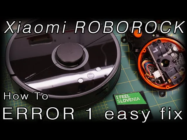
How to Fix Roborock Error 1 (LiDAR Blocked)
Roborock vacuum cleaners report Roborock error 1 lidar error when the Laser Distance Sensor (LDS) turret fails to rotate, spins below its required operating speed (typically 300 RPM / 5 Hz), or fails to receive return pulses from its optical receiver diode. Because Roborock’s SLAM navigation depends on continuous 360-degree laser telemetry to generate floor plans and localize the unit, any mechanical friction around the spindle, a dislodged drive belt, an obstructed optical window, or carbon brush wear inside the 5V DC turret motor will trip roborock lidar error 1 and halt operation immediately.
Quick Diagnostic Matrix
| Symptom | Root Cause | Inspection Point / Tool | Recommended Fix |
| Turret does not spin at all during startup | Hair binding the central spindle, slipped drive belt, or dead spots in the DC motor | LDS Turret Cavity | Perform the manual spin test; inspect the rubber drive belt; jumpstart the DC motor. |
| Turret spins freely, but robot still halts with Error 1 | Dust, hair, or cobwebs blinding the laser diode or receiving optical sensor | Optical Lenses inside Turret | Clean optical sensor windows using 99% IPA or a low-pressure compressed air burst. |
| Error triggers with rapid clicking under furniture | Top radar collision cover microswitch stuck in the depressed/actuated state | Top LDS Bumper Hood | Tap the top orange/black radar cap repeatedly to dislodge stuck micro-springs. |
| Turret twitches back and forth without continuous rotation | Low motor torque caused by oxidized motor commutators or severed driver rail | Multimeter / 9V Battery | Apply direct 9V power to the disconnected motor terminals to burn off carbon scale. |
1. Clear Spindle Obstructions and Clean the Optical Lenses
The most common cause of roborock lidar error 1 is hair or carpet fibers wrapping tightly around the central spindle underneath the rotating orange or black turret housing.
[Roborock LDS Turret Profile]
      ┌─────────────────────────┐
      │   Top Radar Bumper Cap   │ <── Tap to free stuck microswitches
      └──┬───────────────────┬──┘
   ┌─────┴───────────────────┴─────┐
   │ [Laser Emitter]   [Receiver]  │ <── Clean optical apertures (Q-tip + 99% IPA)
   │ ░░░░░░░░░░░░░░░░░░░░░░░░░░░░░ │
   └─────┬───────────────────┬─────┘
         │   Drive Spindle   │ <── Hair wraps around base (inspect with light)
         └───────────────────┘
- Power off the robot by holding the Power button for 3 seconds.
- Shine a bright flashlight into the gap between the rotating turret and the vacuum’s top housing.
- Use a pair of precision tweezers to catch and pull out any hair, dust bunnies, or threads wrapped around the base of the spindle shaft.
- The Manual Spin Test: Gently rotate the turret clockwise and counter-clockwise with your finger. It should spin smoothly with slight magnetic resistance from the motor. If it feels gritty, binds, or stops abruptly, internal fibers are still caught in the lower bearing.
- Inspect the two optical windows inside the turret (the laser diode transmitter and the optical sensor receiver).
- Wipe both lenses gently with a dry cotton swab (or lightly moistened with 99% isopropyl alcohol) to remove aerosolized oil or fine drywall dust.
2. Unstick the Top Radar Collision Cover (Anti-Pinch Bumper)
The protective plastic dome covering the LiDAR turret houses an integrated omnidirectional collision switch. This switch detects when the vacuum attempts to drive under low clearance (such as a sofa or bed frame) to prevent crushing the sensor. If this cover jams downward or collects grit in its pivot springs, the firmware interprets the obstruction as a blocked sensor.
- Press firmly on the top circular cap of the LiDAR housing.
- You should hear and feel an audible, tactile click as the spring-loaded microswitches depress and rebound.
- Tap the perimeter of the cap firmly several times from different angles to release any stuck mechanical switches or dislodge trapped grit beneath the collar.
- If the cap remains loose or fails to spring upward, lift the edge gently with a plastic spudger to reset the internal return springs.
3. Inspect the LiDAR Drive Belt
If the turret refuses to rotate but you hear a faint high-pitched electrical hum when the cleaning cycle starts, the small rubber O-ring driving the turret has snapped, stretched, or slipped off the motor pulley.
[Underneath the LDS Casing]
  ┌──────────────┐                  ┌──────────────┐
  │  LiDAR Turret │══════════════════│  Drive Motor │
  │ (Large Pulley)│   [Rubber Belt]  │(Small Pulley)│
  └──────────────┘                  └──────────────┘
- Remove the dustbin and loosen the top casing screws (usually hidden under rubber screw caps or the central hinge).
- Lift the top cover to expose the circular LDS unit.
- Remove the protective screws holding the upper LDS shroud.
- Inspect the black rubber drive band connecting the turret’s perimeter track to the tiny brass pulley on the adjacent DC motor:
- If the belt slipped off: Hook it back around the motor pulley, rotate the turret by hand to verify alignment, and retest.
- If the belt is broken or loose: Replace it with an OEM Roborock LiDAR replacement belt (or a matching 2.5 mm nitrile rubber O-ring with an internal diameter of approximately 65–70 mm).
4. Perform the 9V Battery “Jumpstart” (Motor Revive Fix)
On older units (such as the Roborock S50, S55, S5 Max, S6, and S7), the small brushed DC motor (standard 3V–5V motor) driving the turret frequently develops dead spots. Microscopic carbon dust from the brushes deposits across the commutator gaps, causing the motor to stall when starting up. A proven roborock lidar error fix involves using a 9V transistor battery to flush carbon scaling off the armature.
[DC Motor Terminal Jumpstart]
 ┌──────────────┐            ┌──────────────┐
 │  9V Battery  │            │  LDS Motor   │
 │   (+)    (-) │            │  (+)     (-) │
 └───┬───────┬──┘            └───┬───────┬──┘
     │       │                   │       │
     └───────┼─── [Red Wire] ────┘       │
             └──── [Black Wire] ─────────┘
      (Pulse power for 5-10 seconds to burn off brush oxidation)
- Unplug the small two-wire molex connector (red and black wires) linking the LiDAR drive motor to the motherboard.
- Take a standard 9V alkaline battery.
- Attach two jumper leads (or wire scraps) to the 9V battery terminals.
- Touch the leads directly to the metal terminals inside the motor’s disconnected plug (Red to
+, Black to-). - The motor will spin at high RPM. Let it run for 5 to 10 seconds, then reverse the polarity (Red to
-, Black to+) for another 5 seconds to clear carbon deposits from both brush faces. - Reconnect the motor plug to the board, reassemble the housing, and start a clean run.
5. Replace the LDS Drive Motor
If the jumpstart procedure fails to resolve the issue, or if the motor only works temporarily before triggering Error 1 again, the internal copper brushes are physically worn out.
- Order a replacement Roborock LDS motor (model usually stamped as
Mabuchi RF-500TBor generic replacement motor with the pre-fitted orange/brass pulley). - Remove the 4 screws securing the LDS module to the robot chassis.
- Turn the module over, unscrew the 2 small Phillips screws securing the motor bracket, and slip off the drive belt.
- Desolder the power leads or unplug the dedicated sub-harness.
- Install the new motor, slip the rubber belt over the pulley, secure the mounting bracket, and ensure correct polarity so the turret spins counter-clockwise during initialization.
[Roborock Mainboard / Sensor Assembly]
 └── Remove Top Shell
      └── Disconnect LDS Assembly (4 Mounting Screws)
           └── Unseat Drive Belt
                └── Swap DC Motor (Mabuchi RF-500TB / 5V DC)
6. Execute a Hard System Reset
If the turret spins smoothly at steady RPM and the optical lenses are spotless, the error can stem from corrupted LiDAR sensor calibration tables in NVRAM following an interrupted over-the-air (OTA) firmware update.
- Open the top lid to access the Wi-Fi LED indicator and the recessed Reset button.
- Press and hold the Home / Dock button on the chassis.
- While continuing to hold the Home button, use a paperclip to press the recessed Reset button once.
- Keep holding the Home button for approximately 5 seconds until the machine announces “Restoring the factory version. This will take about 5 minutes.”
- Release the button and allow the robot to complete its internal operating system re-flash.
- Once rebooted, pair the vacuum back to the Roborock / Mi Home app and start a clean mapping cycle.
If the turret continues to spin steadily at 300 RPM but the vacuum aborts with Error 1 within 10 seconds of starting, the infrared laser diode or the CMOS line sensor on the LDS circuit board has burned out. Because individual laser diode replacement requires precision optical alignment calibration, resolving this failure requires swapping the complete modular LDS turret assembly.