
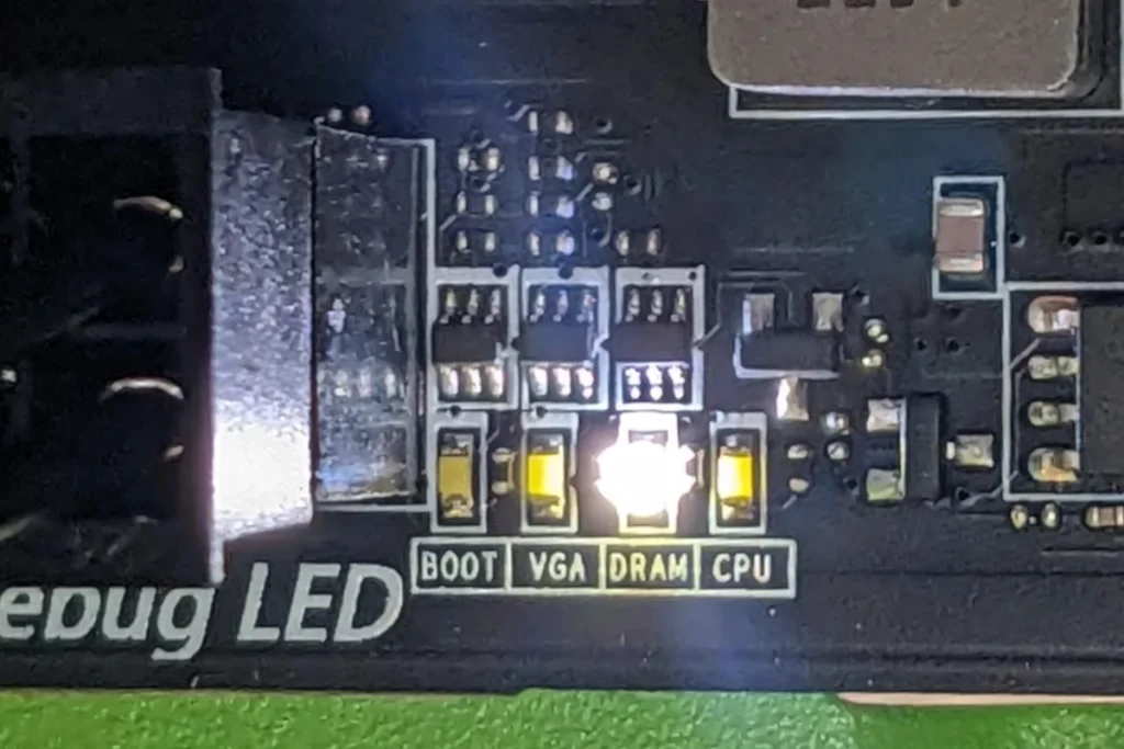
How to Fix RAM Lights Up But DRAM Light On Motherboard
When your RAM RGB lighting illuminates but the motherboard’s DRAM debug LED remains solid amber, yellow, or red, the system is failing its Power-On Self-Test (POST) during memory link training or bus initialization. Because RGB LEDs are powered via separate auxiliary standby traces ($3.3text{V}$ or $5text{V}$ VDD/SMBus pins) at the edge of the module, illumination confirms only that the slot is receiving basic electrical power—it does not indicate that the memory controller has established a valid 64-bit data connection with the memory module.
Quick Diagnostic Matrix
| Symptom | Root Cause | Inspection Point / Setting | Recommended Fix |
| New build; fans spin, DRAM LED steady yellow/amber | Incomplete mechanical seating on single-latch DIMM slots | DIMM Retention Latches | Re-seat RAM firmly; press until both ends lock with an audible click. |
| DDR5 / AM5 platform; black screen for several minutes | Extended memory training cycle after CMOS reset or hardware change | System POST Time | Do not power down. Wait 10 to 15 minutes for memory sub-timing discovery to finalize. |
| DRAM LED turns on after enabling XMP/EXPO in BIOS | Memory controller cannot stabilize selected frequency or primary timings | Motherboard CLR_CMOS / Pins | Clear CMOS via jumper pins to wipe stored overclock profiles and restore defaults. |
| RAM installed in slots 1 and 3 (A1 & B1) | Daisy-chain signal reflection caused by populating non-terminated stub slots | DIMM Slot Layout | Move modules to Slots 2 and 4 (A2 and B2, counting away from CPU). |
| DRAM LED stays on with multiple different RAM kits | Uneven CPU cooler mounting pressure or bent LGA socket pins | CPU Socket & Cooler Screws | Loosen CPU cooler bracket by a quarter-turn; check CPU socket for bent pins. |
1. Re-Seat Modules and Verify Single-Latch Engagement
Most modern motherboards utilize single-latch DIMM slots (latches on the top side only, with fixed plastic grooves on the bottom). This design frequently causes the bottom half of the module to appear seated while sitting fractions of a millimeter out of alignment, leaving the primary data bus disconnected while the RGB power pins make contact.
[Single-Latch DIMM Slot Cross-Section]
 [Moving Top Latch] ──► [Locked]
  ┌──────────────────────────────────────────────────┐
  │ [================ RAM MODULE ================]   │
  └───────────────┬──────────────────┬───────────────┘
   [RGB Power Pins: Connected]   [Data/Clock Pins: Disconnected]
                  │                  │
                  └────► [Bottom Groove: Not Fully Seated]
- Shut down the computer completely and flip the power supply switch to O (Off).
- Unplug the AC power cord from the wall.
- Open the top retention latches and remove the RAM modules completely.
- Align the notch on the RAM stick’s gold contact edge with the raised plastic key in the DIMM slot.
- Seating Technique:
- Insert the bottom (unlatched) edge of the RAM module into the slot groove first at a slight angle.
- Pivot the module flat and place both thumbs on the outer top edges of the RAM heat spreader.
- Apply firm, even, downward pressure until you hear and feel a sharp mechanical click from the top latch.
- Verify visually that the gold contact fingers are completely invisible beneath the slot lip across the entire length of the module.
2. Enforce Primary Daisy-Chain Slot Topology (A2 / B2)
Almost all consumer motherboards (ASUS, MSI, Gigabyte, ASRock) utilize a Daisy-Chain memory trace topology. In this layout, memory signals route from the CPU to Slot 1, then continue to Slot 2, which contains the trace termination resistors.
Populating the intermediate slots (A1 or B1) without populating the end slots leaves an open transmission line that causes electrical signal reflections, preventing memory training:
[CPU Socket] ════► Slot A1 (Stub) ════► Slot A2 (Primary Terminator)
             ════► Slot B1 (Stub) ════► Slot B2 (Primary Terminator)
- For 1 Stick of RAM: Install strictly in Slot A2 (the second slot to the right of the CPU socket).
- For 2 Sticks of RAM: Install strictly in Slots A2 and B2 (Slots 2 and 4, counting outward from the CPU).
- Avoid placing modules in Slots A1 and B1 (Slots 1 and 3) unless you are populating all 4 slots with matched modules.
3. Clear CMOS to Wipe Stale NVRAM & EXPO/XMP Profiles
If you swapped RAM kits, changed CPU coolers, or previously enabled an unstable XMP, EXPO, or DOCP memory profile, the motherboard will attempt to boot using cached memory timings that do not match the physical modules installed.
[Disconnect AC Power]
 └── Press and hold PC Power Button for 15s to drain capacitors
      └── Short CLR_CMOS / JBAT1 pins with metal screwdriver for 15s
           └── (Or remove CR2032 coin-cell battery for 10 minutes)
- Switch off the power supply and disconnect the AC wall cord.
- Press and hold the computer chassis power button for 15 seconds to discharge residual capacitor energy.
- Locate the Clear CMOS pins on the motherboard (labeled
CLR_CMOS,JBAT1, orRESET_BIOS). - Bridge the two bare metal pins with the tip of a flathead screwdriver for 15 seconds.
- Alternative method: Remove the silver CR2032 coin-cell battery from the board, wait 10 minutes, and reinsert it.
- Reconnect power and turn on the PC. The motherboard will wipe its volatile NVRAM tables and reload standard JEDEC baseline memory profiles ($2133text{–}4800text{ MT/s}$).
4. Allow Memory Training to Complete (DDR5 & AM5 Platforms)
On modern platforms (particularly AMD Ryzen 7000/9000 on AM5 and Intel 13th–15th Gen on LGA 1700/1851), clearing the CMOS or swapping memory modules forces the motherboard to perform a comprehensive Memory Context Training cycle.
During this process:
- The monitor displays no signal and enters sleep mode.
- The fans frequently spin at 100% full speed.
- The DRAM debug LED remains solid amber/yellow.
- The memory controller cycles termination resistances, drive strengths, and internal voltage rails across hundreds of combinations to find an electrically stable operating window.
Caution: Do not force-restart or unplug the computer. On high-density configurations (32 GB, 64 GB, or 4 occupied slots), memory training can take between 5 and 15 minutes. Let the system run undisturbed until the DRAM light transitions to VGA or BOOT.
5. Isolate Faulty Hardware via Single-Stick Diagnostic
To isolate whether the issue lies within an individual memory stick, a damaged DIMM slot, or the CPU’s internal memory controller channels, test the hardware sequentially:
- Remove all RAM modules except one single stick placed in Slot A2.
- Power on the system. If it posts successfully, shut down and test the second stick in the same Slot A2.
- If Stick 1 boots but Stick 2 triggers the DRAM LED: Stick 2 is defective (dead on arrival or failed memory chip).
- If both sticks boot individually in Slot A2, but fail when combined: The issue is memory channel communication (proceed to Step 6) or slot B2 is damaged.
- If neither stick boots in Slot A2: Move the stick to Slot B2 and test again to rule out a damaged physical slot.
6. Adjust CPU Cooler Mounting Pressure & Inspect LGA Pins
The Integrated Memory Controller (IMC) is located directly inside the CPU package. Traces for Memory Channel A and Channel B route directly through the motherboard PCB layers from the CPU socket pins to the DIMM slots.
Uneven mechanical pressure from an over-tightened CPU cooler or damaged socket pins will physically decouple the memory controller from the motherboard traces:
[Uneven / Excessive Cooler Torque]
            ▼                 ▼
    ┌───────────────┐ ┌───────────────┐
    │ CPU Cooler    │ │ Mounting Post │
    └───┬───────────┴─┴───────────┬───┘
        ▼                         ▼
   [Warped CPU Substrate] ──► [Loss of Contact on IMC Pin Grid]
                                       │
                                       ▼
                       [DRAM DEBUG LED STAYS SOLID ON]
- Loosen Cooler Screws: If using an aftermarket AIO liquid cooler or heavy air cooler, loosen the four mounting bracket screws by one-half to one full turn. Uneven torque flexes the processor substrate, lifting corner contact pads away from the socket pins.
- Inspect CPU Socket Pins (LGA Sockets):
- If loosening the cooler does not resolve the issue, remove the CPU cooler and carefully unlatch the CPU.
- Use a bright flashlight and magnification to inspect the gold pins inside the motherboard socket (LGA 1700, LGA 1851, or AM5).
- Look for bent, recessed, or crossed pins. Pins located toward the outer edges of the socket typically carry the direct memory channel lines; a single bent pin will kill an entire memory channel and trigger a persistent DRAM light.
- Inspect CPU Contact Pads: Check the underside of the processor for thermal paste smears, dust, or fingerprints. Clean the gold pads gently using a lint-free swab dipped in 99% isopropyl alcohol (IPA).
7. Flash Updated BIOS via Headless USB Flashback
If your motherboard shipped with an older factory BIOS version, its internal memory reference code (AGESA for AMD, MRC for Intel) may lack microcode compatibility for newer high-density modules (such as 24 GB / 48 GB non-binary DIMMs) or newer memory IC revisions (SK Hynix A-die / M-die).
You can flash a newer BIOS without passing POST using USB BIOS Flashback (Q-Flash Plus / Flash BIOS Button):
- On a secondary computer, format a USB flash drive (32 GB or smaller) to FAT32 with an MBR partition scheme.
- Download the latest stable BIOS file from your motherboard manufacturer’s official support page.
- Extract the ZIP file and rename the BIOS binary according to your manufacturer’s hardware flashing requirements:
- ASUS: Run
BIOSRenamer.exeor rename manually (e.g.,creative.CAP). - MSI: Rename the file to
MSI.ROM. - Gigabyte: Rename the file to
GIGABYTE.bin. - ASRock: Refer to manual (commonly left as default or
CREATIVE.ROM).
- Copy only the renamed file to the root of the USB drive.
- Insert the USB drive into the dedicated BIOS Flashback port on the rear motherboard I/O panel (marked with a white outline or label).
- With the PC powered off but the PSU switch turned on, press and hold the BIOS Flashback button for 3 seconds until the LED indicator begins flashing.
- Wait 5 to 8 minutes until the LED stops blinking and turns off completely. Power on the PC and allow several minutes for the refreshed firmware to complete memory initialization.
If the DRAM debug light remains permanently illuminated after testing each stick individually in Slot A2, loosening the CPU cooler, inspecting the socket for bent pins, and updating the BIOS via Flashback, the fault is isolated to silicon hardware failure. This indicates a dead memory channel inside the processor’s Integrated Memory Controller (requiring a CPU RMA) or an open-circuit solder defect underneath the motherboard’s primary DIMM slots.