
How to Fix Corsair Pump Failure Fix
How to Fix Corsair AIO “Pump Failure” Error
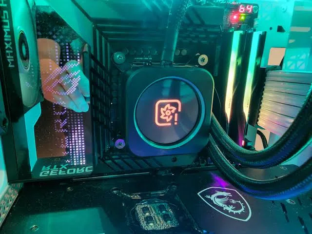
A “Pump Failure” error on a Corsair All-In-One (AIO) liquid cooler (such as the iCUE Elite Capellix, LCD Series, or Hydro H-Series) occurs when the system stops receiving a tachometer speed signal from the pump’s internal Hall-effect sensor, or when the impeller stops spinning entirely. When this happens, iCUE flashes all RGB LEDs bright red, ramps fans to $100%$ emergency mode, and triggers a safety popup.
However, a “Pump Failure” alert is not always a dead pump. It falls into two distinct categories:
- A True Mechanical/Electrical Failure: The impeller motor has seized or lost $+12text{V}$ power, causing immediate thermal runaway where the CPU hits $95^circtext{C}–100^circtext{C}$ and thermal throttles (
PROCHOT) within 60 seconds of boot. - A Telemetry / Connection False Alarm: The pump is running and cooling the CPU normally, but the proprietary 24-pin Commander CORE ribbon cable is unseated, a tachometer pin is loose, or iCUE firmware has stalled the data loop.
Quick Diagnostic Matrix
| Symptom / Behavior | Underlying Cause | Diagnostic Check | Recommended Fix |
| Flashing Red LEDs + CPU hits $95^circtext{C}–100^circtext{C}$ in $<60$s | True mechanical pump failure, seized impeller, or dead $+12text{V}$ rail | Monitor CPU temp in BIOS; touch both AIO tubes | Verify dedicated SATA power; tilt chassis to dislodge air; if cold, initiate RMA. |
| Flashing Red LEDs + CPU temps stay normal ($30^circtext{C}–45^circtext{C}$) | Telemetry loss: Commander CORE 24-pin cable not fully seated or pin bent | Check temps in HWMonitor / BIOS | Power down, unseat and firmly re-click the wide 24-pin cable into Commander CORE. |
| Pump makes rapid clicking, rattling, or gurgling noise | Air pocket (vapor lock) trapped inside the pump cavity around the impeller | Listen to pump block vs radiator | Tilt chassis $45^circ$ while pump runs on Extreme speed to push air into radiator. |
| BIOS shows “CPU Fan Speed Error” on cold boot | Single-pin tachometer sensor cable not plugged into CPU_FAN header | Inspect motherboard CPU_FAN | Plug the 1-pin tachometer lead from the AIO pump block directly into CPU_FAN. |
| Error appeared immediately after an iCUE software update | Corrupted Commander CORE / AIO firmware table or USB communication drop | iCUE Device Settings | Perform a clean iCUE registry uninstall and execute a Forced Firmware Update. |
1. Differentiate True Pump Failure from a Telemetry Glitch
Before dismantling your PC, determine whether your CPU is in imminent thermal danger or if the pump is circulating coolant despite the warning.
[Diagnostic Branch: Check CPU Thermals Immediately]
 ┌────────────────────────────────────────────────────────┐
 │ Boot PC ──► Enter BIOS / UEFI (Monitor CPU Core Temp)   │
 └──────────────────────────┬─────────────────────────────┘
                            │
            ┌───────────────┴───────────────┐
            ▼                               ▼
 [Temp Rises to 90°C–100°C in <60s]   [Temp Stays Stable at 30°C–45°C]
  ├── TRUE MECHANICAL FAILURE         ├── TELEMETRY / FALSE ALARM
  ├── No coolant circulation          ├── Pump is physically spinning
  └── SHUT DOWN IMMEDIATELY           └── Proceed to Sections 2 & 4
- The Temperature Check: Turn on the PC and immediately open your motherboard’s BIOS/UEFI screen or open hardware monitoring software (HWiNFO64 or Core Temp).
- Rapid Thermal Spike ($>85^circtext{C}$ at idle): Shut down the PC immediately. The coolant is static, absorbing heat locally at the copper cold plate until the CPU shuts down to prevent silicon degradation.
- Normal Idle ($30^circtext{C}–50^circtext{C}$): The pump is operating and moving heat into the radiator. The alert is caused by communication loss between the pump head, the Commander CORE, and the motherboard.
- The Tactile Tube Test: Place two fingers gently on the ribbed/sleeved coolant tubes running from the pump block:
- Normal Operation: Both tubes will feel similar in temperature, and you will feel a faint, steady high-frequency vibration from fluid flow.
- Seized Pump: One tube will feel warm or hot to the touch near the CPU block while the other tube and the radiator remain ambient cold.
- Vibration Check: Place your fingertip directly on the center of the Corsair pump cap. A dead pump will feel completely motionless.
2. Re-Seat the Commander CORE 24-Pin Keyed Cable
On Corsair Elite Capellix and LCD models, the pump does not plug directly into the motherboard. It connects to the included iCUE Commander CORE module via a wide, high-density proprietary connector. This connector is the #1 cause of false “Pump Failure” errors.
[Commander CORE Proprietary Interface]
 ┌────────────────────────────────────────────────────────┐
 │ iCUE Commander CORE Hub                                │
 │   ┌────────────────────────────────────────────────┐   │
 │   │ [===== Wide 24-Pin Proprietary Port =====]     │   │
 │   └───────────────────────┬────────────────────────┘   │
 └───────────────────────────┼────────────────────────────┘
                             ▲
              ┌──────────────┴──────────────┐
              │ Keyed Pump Harness Plug     │ <── MUST BE SEATED 100% FLUSH!
              │ (From AIO Pump Block)       │     (Even a 0.5mm gap breaks
              └─────────────────────────────┘      tachometer data pin)
- Power off the PC completely, switch off the power supply, and unplug the AC power cord.
- Locate the Commander CORE hub (typically mounted behind the motherboard tray).
- Inspect the wide, rectangular connector coming from the pump head:
- This connector is keyed, but the outer housing can easily catch on the socket rim, making it appear inserted when the internal pins have not made electrical contact.
- Reseat the Cable:
- Firmly grip the connector and pull it straight out.
- Inspect the male pins on the Commander CORE with a flashlight to verify none are bent or recessed.
- Align the connector and press it into the socket with firm, even pressure until the outer plastic collar sits completely flush against the Commander CORE housing with zero visible gap.
- Inspect the Single-Pin Tachometer Wire:
- Trace the thin single wire coming out of the pump harness.
- Ensure it is firmly plugged into the motherboard’s
CPU_FANheader (notAIO_PUMPorSYS_FAN). This wire transmits the RPM pulse to the motherboard’s Super I/O chip. If the BIOS detects 0 RPM onCPU_FAN, it may halt the system or report false errors.
3. Verify Dedicated SATA Power Delivery
Corsair AIO pumps draw up to $2.0text{A}–2.5text{A}$ across the $+12text{V}$ line under full load, especially models powering 24 addressable RGB LEDs or an IPS LCD display cap.
[Power Delivery Validation]
 Power Supply (PSU) ═════ [Direct SATA Power Cable] ═════► Commander CORE
                                                                 │
                                ┌────────────────────────────────┴──┐
                                ▼                                   ▼
                       [AIO Pump Block]                     [RGB Fans x3 / x6]
- Avoid Daisy-Chaining: Ensure the SATA power connector feeding the Commander CORE is on a dedicated SATA power cable coming directly from the power supply.
- Shared Rail Under-Voltage: If the same SATA power line is shared with multiple mechanical hard drives, fan hubs, or SATA SSDs, the $+12text{V}$ rail can drop under transient loads. When voltage dips below $11.2text{V}$, the pump’s brushless motor controller resets, triggering a pump failure fault in iCUE.
- Avoid Molex-to-SATA Adapters: Never use legacy 4-pin Molex-to-SATA adapters; they frequently lack stable voltage regulation and drop the $3.3text{V}$ line required by some Commander CORE revisions.
4. Clear Vapor Lock & Air Pockets (Gurgling / Rattling Fix)
If your pump is buzzing, grinding, or thermal throttling despite power being supplied, an air pocket is trapped inside the impeller housing (known as vapor lock or cavitation). Centrifugal AIO pumps cannot pump air; when a bubble enters the impeller chamber, the impeller spins in an air pocket, losing fluid prime and stopping all coolant circulation.
[Optimal Radiator Placement (Air Trapped in Radiator, NOT Pump)]

     RECOMMENDED (Top Mount)             ACCEPTABLE (Front Mount)            INCORRECT (Bottom Mount)
  ┌──────────────────────────┐             ┌──┐                        ┌──────────────────────────┐
  │ [=== RADIATOR (TOP) ===] │             │  │ <── Top Tank Higher    │     AIO PUMP BLOCK       │
  └──────────┬──┬────────────┘             │R │     than CPU Block     └──────────┬──┬────────────┘
             │  │                          │A │                                   │  │
             ▼  ▼                          │D │                                   ▼  ▼
      ┌──────────────┐                     │  ├─── Tubes at bottom       ┌──────────────────────────┐
      │   AIO PUMP   │                     │  │    preferred             │   RADIATOR AT BOTTOM     │
      └──────────────┘                     └──┘                          └──────────────────────────┘
   Air rises safely to top           Air stays at top tank,           AIR RISES INTO PUMP CHAMBER:
   of radiator tank.                 away from pump intake.           CAUSES PUMP FAILURE / NOISE!
The Radiator Orientation Rule
- The pump block must never be the absolute highest point of the loop. If your radiator is mounted on the bottom floor of your case, air will rise into the pump block, causing cavitation and pump failure.
- Mount the radiator at the top of the chassis as exhaust, or at the front of the chassis with the radiator tubes positioned at the bottom (or with the top end-tank sitting higher than the CPU block).
The Chassis Tilt Procedure (Clearing Trapped Air)
- Turn on the PC and open iCUE.
- Navigate to your Cooler > Cooling tab, and set the Pump speed to Extreme (forces maximum RPM, typically $2800–3100text{ RPM}$).
- While the pump is running at full speed, pick up the PC chassis and slowly tilt it backward by $45^circ$, hold for 10 seconds, then tilt it forward by $45^circ$, and finally to the side opposite the tubing.
- Mechanism: Tilting the chassis forces the buoyancy of the air bubble to exit the pump’s micro-fin cold plate chamber and travel up the tubes into the radiator end-tank, restoring fluid prime to the impeller.
5. Bypass USB Header Bottlenecks & Fix iCUE Software Faults
Communication drops over the internal motherboard USB 2.0 bus cause iCUE to lose synchronization with the Commander CORE, registering as an immediate pump failure even though hardware operation is fine.
[USB 2.0 Communication Path]
 Commander CORE ──► [Direct 9-Pin Motherboard USB Header] ──► Windows Kernel / iCUE
                           ▲
                           └── DO NOT USE PASSIVE SPLITTERS (Drops Data Packets)
- Connect Directly to Motherboard:
- Plug the Commander CORE’s 9-pin USB connector directly into a native USB 2.0 header on your motherboard.
- If you are using an unpowered, passive Y-splitter cable to share one motherboard header between an AIO, Lian Li hub, or front-panel ports, disconnect the splitter. Passive splitters cause voltage sag on data lines. If you need more ports, install an internal powered USB hub (such as the Corsair Internal 4-Port USB Hub or NZXT Internal USB Hub) that supplies its own SATA power.
- Execute a Clean iCUE Reinstall:
- Close iCUE completely from the Windows system tray.
- Press
Win + R, typeappwiz.cpl, and uninstall Corsair iCUE. - Press
Win + R, type%appdata%, and delete the Corsair folder. - Press
Win + R, type%localappdata%, and delete the Corsair folder. - Restart your PC, download the latest version of iCUE from Corsair’s official website, and install it fresh.
- Perform a Forced Firmware Update in iCUE:
- In iCUE, click the Settings (Gear Icon) in the top right.
- Select Firmware Updates.
- Find your cooler / Commander CORE. Even if it says “Up to date”, click the three dots (…) next to it and select Force Update.
- Critical: Do not disconnect power or shut down during the flash. The pump and fans will spin down briefly and ramp back up once the internal EEPROM is rewritten.
6. Hardware Reset the Commander CORE
If the Commander CORE controller logic is deadlocked in an error state, perform a physical hardware reset:
[Commander CORE Reset Flow]
 Disconnect SATA Power ──► Locate Pin-Hole on Commander CORE Casing
                                    │
                                    ▼
 Depress Internal Micro-Switch with Paperclip ──► Reconnect SATA Power
                                    │
                                    ▼
 Hold Button for 10 Seconds ──► Release ──► Restart PC
- Power off the system completely and unplug the PSU.
- Locate the Commander CORE casing. Near the edge or underside, look for a small recessed pin-hole button (available on specific production batches of Commander CORE and Commander ST modules).
- Use a thin paperclip to press and hold the internal micro-switch.
- While holding the switch down, connect power to the system and turn it on.
- Continue holding the button down for 10 seconds, then release it.
- This forces the device’s microcontroller to reload its factory fallback bootloader.
7. When to RMA (True Hardware Failure Identification)
If your system exhibits all three of the following conditions:
- CPU temperature exceeds $90^circtext{C}$ within 60 seconds of a cold boot, forcing a thermal shutdown.
- One tube is hot to the touch while the radiator remains cold.
- The tachometer reading in both your BIOS (
CPU_FAN) and iCUE reads 0 RPM, and zero vibration is felt on the pump block despite a verified flush connection on the Commander CORE 24-pin cable.
The internal ceramic shaft has snapped, the motor windings have burned out, or the internal drive circuitry has suffered an open-circuit failure. AIO coolers are closed, hermetically sealed loops and cannot be disassembled, refilled, or repaired at home without compromising fluid seals.
- Corsair Warranty: Corsair provides a 5-year manufacturer warranty on all modern AIO liquid coolers (Hydro, Elite Capellix, Elite LCD, and Titan series).
- Filing an RMA: Visit
help.corsair.com, submit a ticket with a screenshot/photo of your BIOS displaying high CPU temperature with 0 RPM on the fan header, along with a copy of your purchase invoice. Corsair provides an advanced RMA or replacement unit covering the full cooler assembly and Commander hub.