
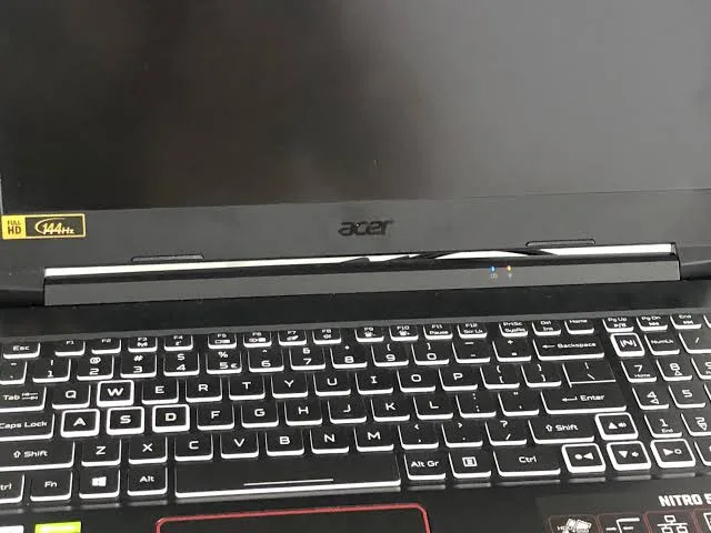
How to Fix Acer Nitro 5 Blinking Orange Light Won T Turn On
A blinking orange (amber) light on an Acer Nitro 5 (typically AN515 or AN517 series) indicates that the Embedded Controller (EC) is locked in an under-voltage state, the battery has fallen below its critical boot threshold, the chassis safety interlock switch is open, or the AC adapter is not delivering the $+19.5text{V}$ main rail.
Quick Diagnostic Matrix
| Symptom / Pattern | Root Cause | Targeted Fix |
| Blinks orange 3–5 times when pressing power button | The charger barrel plug is not fully locked into the recessed port | Push the charger plug firmly until it emits a distinct second mechanical click. |
| Blinks orange continuously while plugged in; no fan/POST | Case safety interlock switch open or loose bottom-cover screw | Tighten all bottom-panel screws (specifically center/RAM bay screws). |
| Blinks orange, alternates with blue, or stays dead | Stalled Embedded Controller (EC) state or flea-power deadlock | Execute a 30-second battery pinhole reset or flea-power drain. |
| Light stays solid orange for 10s, then blinks and cuts out | Battery dropped below critical recovery voltage ($<3.0text{V}/text{cell}$) | Leave on charger undisturbed for 60 minutes without pressing power. |
| No response on battery; blinks orange on AC even after reset | RAM contact oxidation or unseated SODIMM stick | Clean RAM gold fingers with 99% IPA / eraser; test one stick in Slot 1. |
1. The “Two-Click” Charger Port (Most Common Cause)
The DC-in jack on modern Acer Nitro 5 laptops features a tight internal retention clip designed to prevent the cable from slipping out during gaming. Many users push the cable in until it feels seated, but it only makes partial contact with the outer ground sleeve, leaving the center $+19.5text{V}$ pin uncoupled.
[Acer Nitro 5 DC-In Barrel Plug]
 ┌────────────────────────────────────────────────────────┐
 │ Laptop Body Port                                       │
 │    ┌──────────────────────────────────────────────┐    │
 │    │ Outer Ground Sleeve     [Center +19.5V Pin]  │    │
 │    └──────────────────────────────────────────────┘    │
 └───────────────────────────▲────────────────────────────┘
                             │
            ┌────────────────┴────────────────┐
            │ First Resistance: PARTIAL FIT   │ ──► Blinking Orange Light (No Charge)
            │ PUSH HARDER ──► SECOND "CLICK"  │ ──► Solid Orange / Blue (Charging / Full)
            └─────────────────────────────────┘
- Inspect the yellow or black plastic collar of the charger’s barrel connector.
- Push the connector straight and firmly into the charging port on the rear or side of the laptop.
- You must feel and hear a distinct, firm second snap/click.
- The gap between the plastic shoulder of the cable and the laptop chassis should be less than $1text{ mm}$. If seated correctly, the blinking orange light will either turn solid orange (charging) or solid blue (charged).
2. Inspect the Chassis Interlock Safety Switch
Acer Nitro 5 motherboards feature a built-in mechanical safety microswitch (interlock switch) that cuts the battery and charging circuit if the bottom cover is removed or loose, preventing shorts during upgrades.
[Motherboard Interlock Safety Switch Mechanism]
 ┌────────────────────────────────────────────────────────┐
 │ Motherboard Surface                                    │
 │                                                        │
 │      [Micro-Pushbutton Switch (SW1)]                   │
 │                   │                                    │
 │                   ▲                                    │
 │      ┌────────────┴────────────┐                       │
 │      │ Rubber / Plastic Standoff│ <── Protrudes from inner bottom case.
 │      └─────────────────────────┘     If screw is loose = Switch opens =
 └────────────────────────────────────── PERMANENT BLINKING ORANGE / NO POWER!
- Flip the laptop over and inspect all Phillips screws on the bottom panel.
- Ensure every single screw is installed and fully tightened, particularly:
- The screw located in the dead-center of the chassis.
- The screws closest to the RAM/SSD compartment.
- If you recently opened the laptop: The small rubber or mylar pressure pad attached to the inside of the bottom plastic casing may have shifted. Remove the bottom cover, locate the tiny push-button switch on the motherboard (often labeled
SW1or near the RAM slots), verify that the plastic peg on the cover presses it down when closed, and reinstall the cover tightly.
3. Perform a Battery Reset (Pinhole / 30-Second Hold)
If the Embedded Controller (EC) encounters a voltage fluctuation or dirty power delivery state, it trips its hardware protection latch and halts the boot sequence.
[External EC Flea-Power Reset]
 Unplug Charger ──► Disconnect all USB devices / monitors
                          │
                          ▼
 Locate Pin-Hole on bottom casing OR Press and HOLD [Power Button] for 30 SECONDS
                          │
                          ▼
 Wait 15 Minutes (Drains capacitor banks) ──► Plug in OEM Charger (2 Clicks) ──► Power ON
- Models with a Battery Reset Pin-Hole:
- Unplug the AC power adapter and disconnect all USB peripherals.
- Turn the laptop over and locate the small circular pin-hole marked with a battery icon.
- Insert a straightened paperclip into the hole, press down until you feel a soft click, and hold it for 10 seconds.
- Wait 5 minutes, reconnect the AC charger (ensure two clicks), and press the power button.
- Models without a Pin-Hole:
- Unplug the charger and all external cables.
- Press and hold down the physical Power button for 30 to 45 continuous seconds.
- Release the button, wait 5 minutes, reconnect the AC adapter, and boot the system.
4. Hard Disconnect: Main Battery + CMOS Cell
If the external reset does not wake the EC, drain residual capacitance directly at the board level.
[Internal Motherboard Battery Bleed]
 1. Remove bottom panel screws ──► Pry open casing with plastic spudger.
 2. Unplug the main battery connector from the motherboard.
 3. Unplug or desolder the small round CMOS coin-cell battery (if equipped).
 4. Press and hold the Power button for 60 seconds.
 5. Reconnect ONLY the AC adapter (Leave battery disconnected).
 6. Attempt to power on:
      ├── If it boots cleanly ──► Battery is dead/faulty; replace battery.
      └── If it still blinks ──► Proceed to RAM isolation.
- Disconnect the main battery lead from the motherboard socket.
- If your model features a visible small CMOS battery (wrapped in black/blue heatshrink with two twisted wires), unplug it from the board. (Note: Newer revisions embed the RTC into the main pack; disconnecting the main battery serves both functions).
- Hold the power button for 60 seconds to drain flea power.
- Plug in the AC adapter with the battery still disconnected.
- Power on the laptop. If the machine boots directly to Windows, the internal battery pack has suffered an open cell or blown Protection Circuit Module (PCM) and must be replaced.
5. Reseat and Isolate RAM Modules
Corrupted training tables or oxidized DDR4/DDR5 contacts will cause the Nitro 5 to halt during early POST, presenting as an orange or alternating orange/blue light loop.
[RAM Diagnostic Isolation Flow]
 Remove both RAM sticks ──► Clean gold contacts with pencil eraser / 99% IPA
                                    │
                                    ▼
 Insert STICK 1 into SLOT 1 (Push down firmly until side clips click)
                                    │
                                    ▼
 Connect AC Adapter ──► Power on ──► WAIT 90 SECONDS (DDR5 Memory Training)
                                    │
 ┌──────────────────────────────────┴──────────────────────────────────┐
 ▼                                                                     ▼
[System Boots to BIOS]                                       [Still Blinks Orange]
├── Stick 1 & Slot 1 are good.                               ├── Swap Stick 1 to Slot 2.
└── Add Stick 2 to verify dual-channel.                      └── If persistent, test Stick 2.
- Ground yourself and remove the RAM modules from their SODIMM slots.
- Clean the gold contact fingers on both sides of each stick using a clean pencil eraser, followed by a wipe with 99% isopropyl alcohol.
- Blow compressed air through the motherboard RAM slots to remove lint or debris.
- Install one stick only into Slot 1.
- Turn on the laptop and wait up to 2 minutes. On DDR5 models (AMD 6000/7000/8000 series, Intel 12th/13th/14th Gen), initial memory retraining after a power cut causes a black screen with flashing lights for 60–90 seconds before displaying the Acer logo.
6. AC Adapter & Input Rail Verification (Multimeter Check)
If the laptop shows no response after the previous steps, verify the health of the power brick and charging circuitry:
- Test the Adapter Output: Set a multimeter to DC Voltage ($20text{V}/200text{V}$ range). Place the red probe inside the barrel plug pin and the black probe against the outer metal barrel.
- Result: It must read between $+19.0text{V}$ and $+19.8text{V}text{ DC}$. If it fluctuates, reads $0text{V}$, or drops under $15text{V}$ when plugged into the laptop, the power brick’s internal switching regulator has died.
- Short on 19V Main Rail: If the charger’s LED indicator turns off or begins blinking the moment you plug it into the laptop, there is an electrical dead-short on the motherboard (typically a shorted ceramic input capacitor or blown high-side MOSFET on the charging rail), triggering the adapter’s over-current protection (OCP). This requires board-level component replacement.