
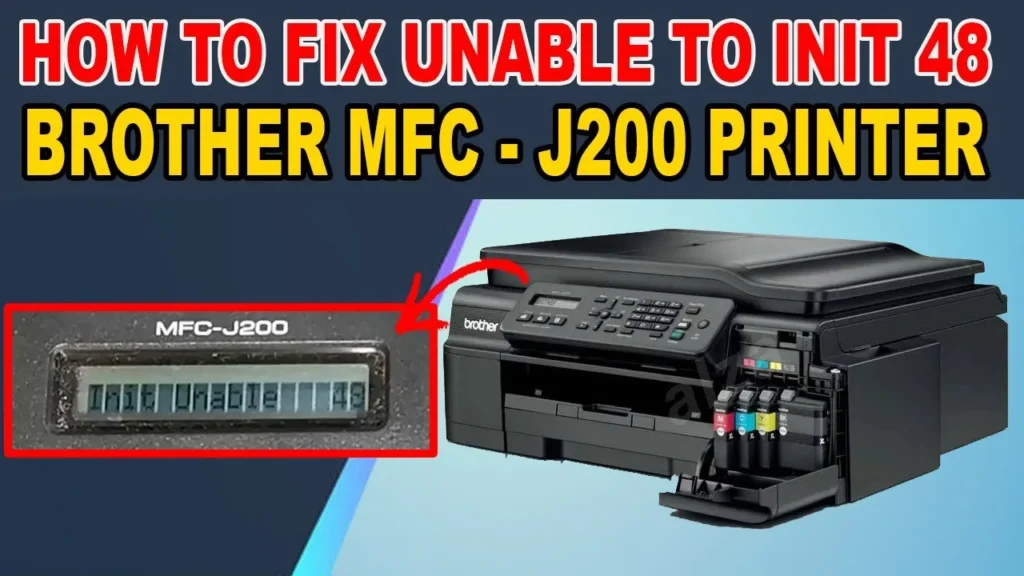
How to Fix Brother Printer “Unable to Print 48”
Brother multifunction and inkjet printers (including the MFC-J, DCP-J, and DCP-T series) display “Unable to Print 48” (also documented as “Machine Error 48” or “Init Unable 48”) when the main logic board (Main PCB) fails its hardware continuity and impedance test across the printhead circuit during the Power-On Self-Test (POST). According to Brother factory service documentation, Error 48 specifically denotes: “Head flat cable detected to be not correctly inserted”.
Quick Diagnostic Matrix
| Symptom | Root Cause | Inspection / Tool | Recommended Fix |
| Error 48 trips instantly at boot before carriage moves | Printhead FFC ribbon disconnected, misaligned, or shorted with aerosolized ink | Carriage Flat Cable (FFC) | Reseat the head flat cable; clean conductive ink residue from pins with 99% IPA. |
| Carriage slams into the right bay, then throws Error 48 | Transmissive optical sensor blinded by ink mist on the clear encoder strip | Timing Slit Film (Encoder Strip) | Clean the clear plastic encoder strip using a dry, lint-free cloth; check tension spring. |
| Error appeared immediately after a severe paper jam | Ripped micro-scraps wedged under the carriage or maintenance capping station | Carriage Track & Purge Bay | Manually slide carriage to the center; remove jammed scraps with precision tweezers. |
| Purge unit gears click loudly during startup | Capping sled or wiper mechanism locked in the raised position | Right Maintenance Station | Manually rotate service station gears forward to drop the purge sled into the home base. |
| Error 48 persists after clearing jams and cleaning cables | Blown piezo drive array on printhead or shorted driver transistors on Main PCB | Hardware Diagnostics / DMM | Inspect printhead for physical burnout; replace the modular printhead or Main PCB. |
1. Execute a Cold Flea-Power Capacitor Drain
Brother printer logic boards preserve error codes inside non-volatile SRAM powered by filter capacitors on the secondary power supply rail. If a momentary carriage hesitation or transient voltage sag triggered Error 48, power-cycling via the front panel will not clear the hardware latch until residual “flea power” is completely drained.
[Printer Powered ON / Showing Error 48]
 └── Disconnect AC Power Cord directly from the wall outlet
      └── Disconnect USB Cable and Network Cable
           └── Press and Hold the physical [Power] button for 60 Seconds
                └── Leave unplugged for 10 Minutes > Reconnect to Wall Outlet
While the machine is powered on and displaying “Unable to Print 48,” pull the power plug directly from the wall outlet.
Disconnect any connected USB interface or Ethernet cables.
Press and hold the physical Power button on the control panel for 60 seconds. This bleeds residual DC current from the logic board’s step-down converters and filter capacitors.
Leave the machine completely unpowered for 10 full minutes to force the internal registers into an un-cached state.
Plug the power cord directly into a dedicated wall outlet (avoid ungrounded extension cords or shared surge strips).
Power on the printer and observe if the initialization cycle completes.
2. Clear Mechanical Obstructions from the Carriage Path
If a torn fragment of paper, paperclip, or dislodged plastic tooth blocks the carriage from reaching its mechanical stops, the stepper motor stalls. Because the printhead electrical calibration sequence executes at specific horizontal physical points, a mechanical stall during this phase triggers Error 48.
[Scanner Unit Lifted Open]
 ┌────────────────────────────────────────────────────────┐
 │ [Left Maintenance Bay]   [Center Track]   [Right Purge Station]│
 │ ░░░░░░░░░░░░░░░░░░░░░    ┌────────────┐    [Capping Sled]      │
 │                          │ Print Head │    [Wiper Blade ]      │
 │                          └────────────┘                        │
 └────────────────────────────────────────────────────────┘
Lift the scanner assembly cover until it locks open securely.
Look inside the chassis for the carriage assembly:
If the carriage is locked in the far-right bay: Plug the power cord in, wait for the carriage to unlock and move toward the center, and immediately pull the power plug to leave it in the open access bay.
Alternative mechanical release: On many Brother models, gently pressing down on the plastic carriage lock lever inside the right housing releases the carriage brake, allowing you to slide it to the center by hand.
Use a bright flashlight to inspect the far-left and far-right corners of the platen. Look underneath the central steel guide rail for tiny shredded paper scraps.
Use blunt plastic tweezers to pull out any trapped paper fibers or foreign debris.
Gently slide the carriage assembly back and forth across the full length of the steel guide rail by hand. It should glide smoothly with uniform, minimal resistance.
3. Clean and Align the Optical Timing Encoder Strip
The optical timing strip (encoder film) is a transparent plastic ribbon suspended horizontally behind the carriage guide rail, printed with microscopic vertical lines. If aerosolized ink mist or roller grease fogs this strip, the transmissive optical sensor on the back of the carriage miscounts motor steps. This causes the carriage to miss its calibration docking points, resulting in Error 48.
[Carriage Rail Profile]
 ┌──────────────────────────────────────────────┐
 │   [======= Clear Plastic Encoder Strip =======]  <── Clean with dry microfiber cloth
 │   [============= Steel Guide Rail ============]  <── Check for smooth travel
 └──────────────────────────────────────────────┘
Ensure the printer is unplugged from AC power.
Locate the narrow, clear plastic band running horizontally across the chassis cavity, positioned just above and behind the steel guide rail.
Inspect the strip:
Verify it is securely hooked onto the metal anchor tabs on both the left and right ends, held taut by the left tension spring.
Verify that the strip passes directly through the center of the optical sensor slot mounted on the rear of the carriage assembly.
Take a clean, dry, lint-free microfiber cloth. (Do not use water, alcohol, or chemical solvents on the strip, as they will dissolve the printed microscopic grid lines).
Gently pinch the clear strip between your thumb and index finger using the cloth, and wipe smoothly along its length from right to left.
Caution: Support the strip lightly with your other hand to avoid bending it or popping the delicate spring off the left bracket.
4. Reseat and Clean the Printhead Flat Flexible Cable (FFC)
Because the primary diagnostic definition of Error 48 in the Brother service manual is a “Head flat cable connection failure,” verifying physical ribbon cable integrity is the core hardware step. High-frequency motion causes the flexible cable to flex millions of times, which can unseat the connector or cause ink mist to penetrate the terminal pins.
[Carriage PCB / Printhead Connection]
 ┌───────────────────────────────┐
 │   Carriage Daughterboard      │
 │   ┌───────────────────────┐   │
 │   │ [=== FFC Socket ===]  │   │ <── Unlatch collar / Inspect pins
 │   └──────────┬────────────┘   │
 └──────────────┼────────────────┘
                ▼
      [White Flat Ribbon Cable]   <── Wipe gold fingers with 99% IPA
With the machine unplugged, slide the printhead carriage into the center of the printer bed.
Release the plastic retaining tabs or remove the single Phillips screw securing the upper protective cover/shield over the carriage PCB assembly.
Locate the white multi-conductor Flat Flexible Cables (FFCs) running into the printhead daughterboard:
Carefully unseat the ribbon cables from their zero-insertion-force (ZIF) or friction sockets.
Inspect the gold-plated contact fingers on the ends of the cables:
Look for black carbon corrosion, bent copper traces, or dark liquid ink bridging adjacent pins.
Dampen an optical swab or lint-free wipe with 99% isopropyl alcohol (IPA).
Gently scrub the gold contacts on the ribbon cable and clean the inside of the connector receptacle.
Allow all contacts to air-dry completely for 5 minutes.
Insert the ribbon cables straight and completely into their sockets (ensure they are not seated at an angle) and lock the retaining collars back in place.
5. Free the Capping Sled and Maintenance Purge Unit
The purge unit on the far-right side houses the rubber suction caps, ink purge pump, and wiper blades. If waste ink dries into a thick, sticky sludge along the cam gear tracks, the capping sled can freeze in the upward position, blocking the printhead from seating flush over the maintenance station.
[Right Maintenance Cavity]
 └── Slide Carriage manually to the far left
      └── Inspect Right Bay for Hardened Waste Ink Sludge
           └── Rotate White Plastic Spur Gears Forward
                └── Purge Sled Lowers Flush into Chassis Floor
Slide the printhead carriage all the way to the far-left bay.
Shine a flashlight down into the right-hand service station cavity.
Inspect the rubber capping cups:
If coagulated, tar-like waste ink has accumulated on the guide tracks, dampen a cotton swab with warm distilled water and dissolve the buildup around the perimeter of the rubber seals.
Locate the white plastic spur drive gears at the rear or side of the purge assembly.
Using a gloved finger or wooden probe, rotate the gears forward (toward the front of the machine):
This manual cycle advances the internal cam, lowering the capping sled down into the bottom of the chassis.
Slide the carriage back into the right bay by hand to confirm that it docks over the station without hitting any raised plastic edges.
6. Clear Error Logs via Brother Maintenance Mode
If the physical cable has been reseated and the carriage travels freely, the firmware may continue displaying “Unable to Print 48” until the latched fault register is reset inside the service menu.
[Enter Brother Maintenance Mode]
 ├── Touchscreen Models: Hold [Home] 5s > Tap blank bottom box > Enter [*2864]
 └── Button Models: Press [Menu] > [Mono Start] > [Up Arrow 4 times]
      └── Display reads: "MAINTENANCE"
           ├── Enter [80] ──► Inspect Error Codes (Verify 48 / 4F)
           └── Enter [99] ──► Force Cold System Reset & Exit
For Touchscreen Models:
Turn on the printer until the error screen appears.
Press and hold the physical Home icon button on the touchscreen bezel for 5 seconds until the display changes to show four serial/ROM rows.
Tap and hold the empty blank rectangular bar at the very bottom of the touchscreen for 3 seconds until a number keypad appears.
Input the universal Brother maintenance sequence:
Plaintext* 2 8 6 4The machine will beep, and the screen will display MAINTENANCE.
Type
80using the keypad to enter the diagnostic error log. Press the Mono Start button repeatedly to scroll through past machine error codes and verify Error 48.Press Stop/Exit to return to the root
MAINTENANCEscreen.Enter
99on the keypad:Mechanism: Command 99 clears temporary hardware fault parameters from non-volatile memory, exits Maintenance Mode, and initiates a full factory reboot sequence.
For Non-Touchscreen / Button-Only Models:
Ensure the printer is plugged in.
Press the buttons in rapid sequence: Menu > Mono Start > Up Arrow (▲) > Up Arrow (▲) > Up Arrow (▲) > Up Arrow (▲).
The display will read ||| MAINTENANCE |||.
Enter
9then9on the numerical keypad (or use the arrow keys to select99and pressOK) to execute the factory restart.
If the printer immediately triggers “Unable to Print 48” during the initial 3 seconds of boot—even after cleaning the encoder strip, verifying smooth carriage movement, and reseating the FFC ribbon cable—the fault is an unrecoverable electrical failure.