
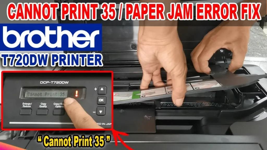
How to Fix Brother Printer “Cannot Print 35” Error
Brother printer error “Cannot Print 35” (also displayed on the LCD panel as “Unable to Print 35”, “Machine Error 35”, or “Init Unable 35”) designates an abnormal stop of the printhead carriage unit during non-discharge/idle positioning.
Quick Diagnostic Matrix
| Symptom | Root Cause | Inspection / Tool | Recommended Fix |
| Error 35 trips immediately at boot before carriage moves | Hardened ink mist or grease fogging the clear timing slit film (encoder strip) | Optical Encoder Strip | Clean strip with a dry, lint-free microfiber cloth; verify strip sits inside the sensor slot. |
| Carriage moves an inch, hesitates, and displays Error 35 | Ripped paper scrap or paperclip jammed in platen tracks or behind carriage | Carriage Track & Rear Bay | Release carriage; clear obstructions using tweezers; inspect rear Jam Clear cover. |
| Purge unit grinds/clicks on the right side during POST | Capping sled or wiper mechanism locked in the elevated maintenance position | Right Purge Station | Rotate white spur drive gears forward to lower the purge sled flush to the chassis floor. |
| Carriage glides with heavy drag across the steel rail | Dried factory grease and paper dust causing mechanical motor overcurrent | Main Steel Guide Rail | Wipe guide rail clean with 99% IPA; apply 2 drops of synthetic PTFE oil. |
| Mechanical path clear, but Error 35 persists across power cycles | Non-volatile SRAM fault register latched in firmware memory | Maintenance Mode Keypad | Enter Maintenance Mode (*2864); inspect log with 80; clear fault latch with 99. |
1. Execute a Cold Flea-Power Circuit Drain
Brother inkjet logic boards store persistent error codes in volatile SRAM powered by high-capacity capacitors on the internal low-voltage power supply rail. If an electrical dip or momentary mechanical resistance triggers Error 35, merely cycling the front power button leaves residual “flea power” in the circuitry, causing the bootloader to reload the error state immediately.
[Printer Displaying Error 35]
 └── Disconnect AC Power Cord from Wall Outlet
      └── Unplug USB and Ethernet Interface Cables
           └── Press and Hold [Power] Button for 60 Seconds
                └── Leave Unplugged for 10 Minutes > Reconnect Direct to Wall Socket
While the printer is powered on and displaying “Cannot Print 35,” disconnect the power cable directly from the AC wall outlet.
Disconnect any USB cables or Ethernet cables running to your PC or network.
Press and hold the physical Power button on the control panel for 60 seconds. This drains the step-down transformers and filter capacitors on the Main PCB.
Leave the machine completely unpowered for 10 full minutes to force volatile hardware registers to clear.
Plug the power cord directly into a dedicated wall outlet (bypass ungrounded extension cords or multi-outlet power strips that cause micro-voltage sags during motor startup).
Power on the printer and check if the initialization routine completes.
2. Clear Obstructions from the Carriage Path and Rear Platen
The primary physical cause of Brother Error 35 is paper debris, staples, or foreign matter wedged under the carriage assembly or inside the platen channels.
[Chassis Interior Under Scanner Unit]
 ┌────────────────────────────────────────────────────────┐
 │ [Left Park Area]         [Center Printing Bed]         [Right Purge Station] │
 │ ░░░░░░░░░░░░░░░░░        ┌────────────┐        [Capping Sled]        │
 │                          │ Print Head │        [Wiper Blade ]        │
 │                          └────────────┘                              │
 └────────────────────────────────────────────────────────┘
Lift the scanner cover using the plastic finger grips until the mechanical support arm locks in the upright position.
Locate the printhead carriage:
If the carriage is locked in the right service station: Connect power, wait for the carriage to unlock and step toward the center, and immediately pull the power plug.
Alternative manual release: On the right side of the carriage bay, push down lightly on the white plastic carriage lock lever to release the mechanical brake, then slide the carriage to the middle by hand.
Use a bright flashlight to inspect the platen (the black ribbed plastic track beneath the carriage):
Inspect the far-left and far-right corners for torn paper corners, sticky label remnants, or paperclips.
Inspect the small silver platen springs underneath the carriage bed to verify they have not popped out of their retaining notches.
Move the printer around and open the Jam Clear Cover (or rear flap) at the back of the chassis.
Remove any paper scraps jammed in the rear feed rollers, clear any dust, and snap the rear cover firmly back into place until both retention clips click.
3. Clean and Re-Seat the Optical Timing Encoder Strip
The CR Timing Slit Film (encoder strip) is a semi-transparent plastic ribbon suspended across the entire carriage width. It is etched with thousands of microscopic vertical grid lines that the carriage’s optical sensor counts to determine position and velocity. Aerosolized ink mist, dust, or grease flung from the drive belt obscures these lines, causing the sensor to lose position tracking during idle passes, triggering Error 35.
[Carriage Sensor & Encoder Strip Profile]
 ┌──────────────────────────────────────────────┐
 │   [======= Clear Plastic Encoder Strip =======]  <── Wipe gently with dry cloth
 │   [============= Steel Guide Rail ============]  <── Lubricate with synthetic oil
 └──────────────────────┬───────────────────────┘
                        ▼
            ┌───────────────────────┐
            │ Carriage Sensor Slot  │ <── Strip must sit dead-center in optical channel
            └───────────────────────┘
Disconnect the printer from AC power.
Locate the clear, narrow plastic strip positioned slightly behind and above the steel guide rail.
Inspect the Strip’s Position:
Verify that the strip is suspended straight under spring tension and hooked securely onto the metal anchor tabs at both chassis walls.
Ensure the strip passes directly through the narrow slot of the optical photo-interrupter mounted on the rear of the carriage. If it has slipped out, unhook the left spring, thread the strip back into the sensor slot, and re-anchor it.
Take a dry, lint-free microfiber cloth or clean optical lens wipe.
Critical: Do not use water, alcohol, window cleaner, or degreasers. Solvents will permanently dissolve the microscopic optical index lines printed onto the plastic film.
Pinch the clear strip gently between your thumb and forefinger using the dry microfiber cloth.
Wipe smoothly from the left anchor toward the right side. Hold the strip steady with your other hand to prevent bending it or unhooking the tension spring on the left bracket.
4. Clean and Lubricate the Carriage Guide Rail
Over time, factory grease on the steel carriage rail combines with airborne paper dust, forming a thick, gummy sludge. This sludge increases friction, causing the carriage motor to draw excessive current during high-speed return movements, which the firmware interprets as an unexpected stall (Error 35).
Unplug the printer and slide the printhead carriage to the center of the bed.
Inspect the horizontal steel guide rail that supports the carriage:
Look for blackened grease ridges or lint buildup along the top and underside of the rod.
Lightly moisten a clean lint-free cloth with 99% isopropyl alcohol (IPA) and wipe down the exposed steel rail to strip off old, contaminated lubricant.
Slide the carriage to the far left and clean the right section of the rail; slide it to the far right and clean the left section.
Apply 2 to 3 drops of synthetic PTFE-based oil (or high-grade mechanical sewing machine oil) along the top surface of the rail.
Caution: Never use WD-40, silicone spray, or automotive grease. These degrade the carriage’s internal POM plastic bushings and attract paper dust.
Slide the carriage back and forth by hand 5 to 6 times to distribute the lubricant evenly across the internal bushings.
5. Free and Lower the Purge Maintenance Station
The purge unit located in the right-side cavity houses the ink suction caps, wiper blades, and purge cam gear train. If waste ink coagulates on the cam tracks, the capping sled can become stuck in the raised position. When the carriage attempts to park or traverse past the station, it collides with the raised sled, triggering code 35.
[Right Maintenance Cavity]
 └── Slide Carriage manually to the far-left bay
      └── Inspect Right Cavity for Hardened Waste Ink Sludge
           └── Rotate White Plastic Spur Gears Forward
                └── Purge Sled Lowers Flush into Chassis Floor
Slide the printhead carriage all the way to the far-left bay.
Shine a flashlight down into the right-hand service station cavity.
Inspect the rubber capping cups and wiper blades:
If thick, tar-like ink deposits surround the sled, moisten a cotton swab with warm distilled water and dissolve the buildup along the sled’s perimeter tracks.
Locate the white plastic spur drive gears on the side or rear of the purge unit.
Using a gloved finger or non-conductive wooden probe, rotate the gears forward (toward the front of the printer):
This mechanical cycling advances the purge cam, forcing the capping sled to drop down into its recessed home position.
Slide the carriage back into the right bay by hand to confirm that it nests cleanly over the maintenance unit without striking any raised plastic or rubber stops.
6. Clear Stored Error Logs via Brother Maintenance Mode
If all mechanical paths are clear, the encoder strip is spotless, and the carriage glides freely, the printer’s non-volatile memory (EEPROM/NVRAM) may still be locked in a latched fault state. Entering Brother Maintenance Mode allows you to review the internal diagnostic log and perform a factory system reset.
[Enter Brother Maintenance Mode]
 ├── Touchscreen Models: Hold [Home] 5s > Tap blank bottom bar > Enter [*2864]
 └── Button Models: Press [Menu] > [Mono Start] > [Up Arrow (▲) 4 times]
      └── Display reads: "MAINTENANCE"
           ├── Code [80] ──► Inspect Sensor States & Machine Error Logs
           └── Code [99] ──► Clear Fault Register & Exit to Normal Boot
Method A: Touchscreen Models (MFC-J / DCP-J Series)
Turn on the printer until the error screen appears.
Press and hold the physical Home icon button on the touchscreen bezel for 5 seconds until the screen changes to show four lines of serial and firmware data.
Tap and hold the empty, blank rectangular space at the bottom of the display for 3 seconds until the numerical keypad appears.
Input the universal maintenance access sequence:
Plaintext* 2 8 6 4The machine will beep, and the screen will display MAINTENANCE.
Type
80to enter the diagnostic log. Press the Mono Start button repeatedly to scroll through past machine error codes to verify when Error 35 was tripped.Press the Stop/Exit button to return to the root
MAINTENANCEscreen.Type
99on the keypad. The printer will execute an internal memory check, flush temporary fault flags, and restart into standard operational mode.
Method B: Button-Only Models (DCP-T / DCP-L Series)
Ensure the printer is plugged in.
Press the control panel buttons in rapid sequence:
Menu > Mono Start > Up Arrow (▲) > Up Arrow (▲) > Up Arrow (▲) > Up Arrow (▲).
The LCD display will read ||| MAINTENANCE |||.
Enter
9then9using the number keys (or scroll to99with arrow keys and press OK).The printer will perform a soft reset and reboot its operating system.
If the printer immediately triggers “Cannot Print 35” upon startup—accompanied by a high-pitched motor whine or an immediate mechanical shudder without carriage motion—the fault is an unrecoverable electrical or electromechanical failure. This indicates an open-circuit failure in the carriage DC motor windings, stripped teeth on the motor’s brass drive pinion, or a blown motor driver transistor on the Main PCB, requiring replacement of the carriage drive motor assembly or the mainboard.