
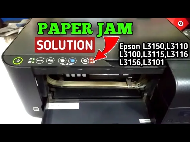
How to Fix Epson L3150 Paper Red Light Blinking
On the Epson EcoTank L3150, a blinking red Paper LED (the icon showing a sheet of paper with a folded corner) indicates that the mainboard’s firmware has registered a paper handling fault: the Page End (PE) optical sensor did not detect paper arriving within the expected timing window, detected an unexpected continuous sheet (paper jam), or registered an abnormal paper feed motor ($PF$) speed variation. When the pickup roller slips against the paper stack, a torn scrap wedges into the feed path, the mechanical sensor flag binds, or the transparent circular timing disk on the left side of the chassis becomes contaminated with ink mist, the printer halts the print queue and flashes the red error indicator.
Quick Diagnostic Matrix
| LED Behavior | Root Cause | Inspection / Tool | Recommended Fix |
| Paper LED blinks alone; printer does not feed | Paper feed roller glazed with dust, or tray is empty/misaligned | Rear Feed Tray & Rubber Rollers | Clean the rubber pickup roller with a damp, lint-free cloth; fan paper stack. |
| Paper LED blinks alone; paper feeds and ejects blank immediately | PE sensor flag displaced, unhooked return spring, or paper size mismatch | Mechanical PE Sensor Flag | Reseat PE sensor flag spring; verify printer driver paper size matches loaded media. |
| Paper LED and Ink LED blink simultaneously | Carriage obstruction, foreign object (coin/clip) in feed path, or encoder strip dirty | Chassis Interior / Rear Chute | Remove debris with tweezers; clean the horizontal carriage timing encoder strip. |
| Paper LED and Ink LED blink alternately | Waste ink pad counter in the mainboard’s EEPROM has reached $100%$ saturation | Maintenance Box Status | Reset the waste ink counter via Epson Adjustment Program or WIC Reset. |
| Power LED + Paper LED + Ink LED flash rapidly together | Fatal hardware error: PF motor failure, seized gear train, or disconnected sensor | Mainboard / Motor Drives | Check for mechanical lockups; inspect PF motor winding resistance and sensor FFC cables. |
1. Interpret the LED Blinking State
Before dismantling the feed mechanism, determine the exact error category by isolating the LED pattern on the control panel:
[Epson L3150 Control Panel LED Decoding]
 ┌────────────────────────────────────────────────────────┐
 │ ( ) Power LED    (•) Paper LED [BLINKING]   ( ) Ink LED│ ──► Standard Paper Feed / Jam / PE Sensor Error
 ├────────────────────────────────────────────────────────┤
 │ ( ) Power LED    (•) Paper LED [BLINKING]  (•) Ink LED │ ──► SIMULTANEOUS: Carriage Jam or Foreign Object
 │                  └─────────── SYNC ─────────┘          │
 ├────────────────────────────────────────────────────────┤
 │ ( ) Power LED    (•) Paper LED [BLINKING]  (•) Ink LED │ ──► ALTERNATE: Waste Ink Pad Counter Saturated
 │                  └─── PING-PONG BLINK ──────┘          │
 └────────────────────────────────────────────────────────┘
Paper LED Blinking Alone: The fault is strictly isolated to the paper path, pickup rollers, or PE detection sensor.
Paper LED and Ink LED Blinking Simultaneously: The printer has encountered a general paper jam or mechanical carriage lock. The printhead cannot traverse cleanly, or a foreign object is obstructing the roller drive gear.
Paper LED and Ink LED Blinking Alternately: The hardware is operational, but the waste ink pad counter is full. Proceed directly to Section 6.
2. Clear Foreign Debris from the Rear Feed Path
The EcoTank L3150 uses a gravity-fed vertical rear paper chute. Loose paperclips, staples, torn scraps from prior jams, and dust frequently fall directly into the feed chute, jamming the pickup cam mechanism.
[Rear Paper Chute Cross-Section]
      [Paper Stack Input]
               │
               ▼
   [Plastic Retractable Gate]
               │
 ┌─────────────┼─────────────┐
 │ ░░░░░░░░░░ [X] ░░░░░░░░░░ │ <── Check here: Foreign Object / Paperclip
 └─────────────┬─────────────┘
               ▼
     [Rubber Pickup Roller]
               │
               ▼
       [Platen / Print Bed]
Power off the printer and disconnect the AC power cord.
Pull the rear paper support up and tilt the printer slightly forward.
Shine a high-intensity flashlight down into the rear paper feed chute:
Look between the feed guide ribs for small foreign objects (coins, staples, plastic pen caps).
Even a tiny $2text{ mm}$ scrap of torn paper trapped under the sub-roller will hold the mechanical sensor open.
Use long, non-magnetic precision tweezers to extract any lodged debris.
Manually raise and lower the blue/gray plastic edge guide to ensure it slides freely along its track.
3. Clean and Deglaze the Paper Pickup and Separation Rollers
Over time, paper dust (calcium carbonate powder) and ambient oils coat the gray D-shaped rubber pickup roller. The roller loses frictional traction against the paper stack, spins without grabbing a sheet, and causes the PE sensor to register a “Paper Out / Feed Failure” error.
[Internal Roller Assembly Under Scanner Unit]
 ┌────────────────────────────────────────────────────────┐
 │ Scanner Unit Lifted (Secured by Prop Arm)             │
 │                                                        │
 │        ┌──────────────┐                                │
 │        │ CR Carriage  │                                │
 │        └──────────────┘                                │
 │                                                        │
 │     [====== Rubber Pickup Roller (LD Roller) ======]   │ <── Clean with damp cloth
 │     [====== Retard / Separation Roller Pad  ======]   │
 └────────────────────────────────────────────────────────┘
Disconnect the printer from AC power.
Lift the scanner assembly upward until the mechanical support arm engages.
Locate the gray rubber feed roller centered toward the rear feed chute:
Inspect the rubber surface for a white/powdery coating or shiny glazing.
Lightly dampen a clean, lint-free microfiber cloth or foam swab with distilled water.
Caution: Never use alcohol, acetone, or petroleum solvents on the rubber rollers. Solvents dry out the natural elastomer, causing cracking, loss of tackiness, and permanent feed failure.
Press the damp cloth against the rubber roller and rotate the roller manually toward the front of the printer to clean the entire outer circumference.
Clean the small separation (retard) pad mounted beneath the main roller.
Allow the rubber to air-dry completely for 5 minutes before reloading high-quality $75text{–}80text{ g/m}^2$ copy paper.
4. Inspect and Reseat the Mechanical PE Sensor Lever
The Page End (PE) sensor monitors paper movement through the print engine. It consists of an optical photo-interrupter switch mounted on the main chassis and a black plastic mechanical swing-arm (flag) with a micro-tension spring. If paper is pulled backward out of the tray during a jam, the flag can flip backward or detach from its spring, holding the optical switch open.
[PE Sensor Flag Mechanism]
 [Paper Entering Path] ──► Hits Flag ──► Flag Swings Down ──► Clears Optical Slot (Sensor: "Paper Present")
                                 ▲
                                 └── [If Spring Drops: Flag hangs down; triggers constant Paper Jam]
With the scanner unit lifted, look directly into the central platen cavity (behind the carriage guide rod).
Locate the thin black plastic finger/flag protruding through the bottom black plastic ribbing along the paper path.
Gently nudge the plastic lever with a cotton swab:
Normal Action: The lever should move forward smoothly with minimal resistance and immediately spring back to its resting vertical position when released.
Broken / Unhooked Spring: If the lever feels loose, flops forward without returning, or rests flat against the platen, its micro-coil return spring has detached.
If detached, use fine tweezers to loop the spring back onto the plastic anchor post on the lever and the chassis frame.
If the flag is bent or broken from forceful paper removal, it will permanently block the optical sensor, requiring replacement of the sensor lever assembly.
5. Clean the Circular PF Rotary Timing Encoder Disk
The Paper Feed ($PF$) motor tracks roller rotation and paper position using a clear, circular plastic disk etched with fine radial lines. This disk is located on the far-left interior side of the printer chassis. If grease, ink mist, or stray lubricant contaminates this disk, the optical reader miscounts the lines, causing the printer to stop mid-feed and flash the paper light.
[Left Chassis Interior Profile]
 ┌────────────────────────────────────────────────────────┐
 │ Left Side Frame                                        │
 │   ┌────────────────┐                                   │
 │   │  Circular PF   │ <── Clear Mylar Disk with Radial Lines
 │   │  Encoder Disk  │     (Wipe gently with dry microfiber)
 │   └───────┬────────┘                                   │
 │           ▼                                            │
 │   ┌───────────────┐                                    │
 │   │ Optical Reader│ <── Photo-interrupter Sensor Slot  │
 │   └───────────────┘                                    │
 └────────────────────────────────────────────────────────┘
Ensure the printer is completely powered off and unplugged.
Remove the left exterior plastic housing of the printer:
Remove the single Phillips screw on the rear left side.
Unclip the plastic tabs along the lower chassis edge and slide the left side panel away.
Locate the large, transparent plastic wheel (the PF timing disk) mounted to the end of the primary roller drive shaft.
Inspect the disk under a light:
Look for black ink splatters, fingerprints, or smears of clear gear grease.
Take a dry, clean lint-free optical wipe:
Critical Caution: Do not use isopropyl alcohol, glass cleaner, or solvents. Solvents dissolve the microscopic printed timing ticks printed on the plastic film.
Gently pinch the disk between the dry wipe and slowly rotate the gear train by hand to clean the entire surface.
Use a dry foam swab or gentle compressed air to clean any accumulated paper dust out of the U-shaped optical reader slot through which the disk passes.
Reattach the side casing and run a test print.
6. Resolve Alternate Blinking (Reset Waste Ink Pad Counter)
If the Paper LED and Ink LED are blinking alternately (one turns on while the other turns off, in a steady back-and-forth pattern), the issue is not a physical paper jam. The printer’s internal safety counter has reached its limit, and the waste ink absorbers in the base must be serviced.
[Waste Ink Counter Reset Workflow]
 1. Connect L3150 to a Windows PC via USB-B Data Cable (Wi-Fi resets will fail).
 2. Download and launch Epson Adjustment Program (AdjProg.exe) or WIC Reset.
 3. Select Model: "L3150" ──► Particular Adjustment Mode.
 4. Navigate to: "Waste ink pad counter" ──► Check "Main pad counter".
 5. Click "Initialize" ──► Turn off printer when prompted ──► Restart.
Connect the Epson L3150 to a Windows PC using a standard USB cable (firmware initialization cannot be completed over Wi-Fi).
Launch the Epson Adjustment Program (AdjProg) for L3150:
Click Select and confirm the port is set to USB (L3150 Series).
Click Particular Adjustment Mode.
Under the Maintenance section, select Waste ink pad counter and click OK.
Check the box labeled Main pad counter.
Click the Check button to read the current state:
The utility will display the point count and percentage (typically $100%$ or $>6346$ points).
Check the box next to Main pad counter again, and click the Initialize button.
Click OK on the confirmation prompt to write the reset byte to the EEPROM.
When the prompt displays “Please turn off the printer”, press the physical Power button on the printer control panel to shut it down.
Close the software, wait 10 seconds, and power the printer back on. The alternate blinking will clear, and the printer will return to a steady green Power light.
If the Paper LED continues to blink immediately upon startup—accompanied by a high-pitched motor whine or a brief shudder from the rear pickup assembly without roller rotation—the paper feed drive mechanism has sustained an electromechanical breakdown. This indicates a stripped tooth on the reduction gear cluster, an open-circuit fault in the $PF$ DC motor windings, or a blown dual-channel motor driver IC (e.g., the E09A92GA driver chip) on the main logic board, requiring physical replacement of the drive gear assembly or the mainboard.