
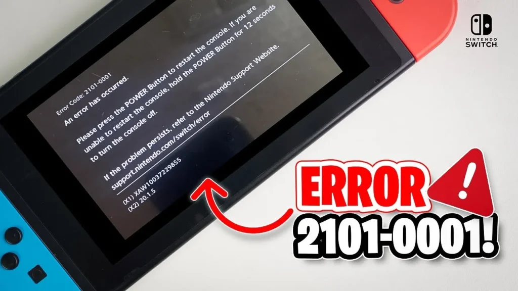
How to Fix Nintendo Switch Error Code 2101-0001
How to Fix Nintendo Switch Error Code 2101-0001
A Nintendo Switch error code 2101-0001 (and the broader Nintendo error code 2101 series) is a fatal kernel panic indicating an $I^2C$ (Inter-Integrated Circuit) communication bus failure or Power Delivery timeout with the ROHM M92T36 power management IC. During initial boot stages, the Horizon operating system queries onboard peripheral controllers across low-voltage $I^2C$ serial lines. If the NVIDIA Tegra X1 processor receives a negative acknowledgment (NACK), detects voltage drop below logic thresholds ($<3.3\text{V}$) on clock/data lines, or encounters an interrupt triggered by an internal rail short, the console halts execution immediately to prevent catastrophic overvoltage damage to the SoC.
In over 90% of field repairs, a Nintendo Switch error code 2101 originates from a physically degraded USB Type-C port or a blown M92T36 USB-PD controller IC. This breakdown occurs when damaged internal port pins short the $+15\text{V}$ $V_{BUS}$ power rail directly into low-voltage communication pins, or when substandard third-party docks and uncertified chargers deliver unregulated transient voltage spikes.
Quick Diagnostic Matrix for Nintendo Error Code 2101
| Symptom / Context | Root Cause | Inspection / Tool | Recommended Fix |
| Error triggers suddenly after a freeze; port appears clean | Transient power-state latch or residual motherboard flea power | Hardware Buttons | Execute a Hard Flea-Power Reset (hold Power 20s; disconnect charger). |
| Error 2101 appears immediately after inserting a MicroSD card | Corrupted MicroSD filesystem or bent card reader pins shorting the $3.3\text{V}$ rail | MicroSD Slot | Eject the MicroSD card; inspect socket pins; test clean boot without media. |
| Nintendo Switch error code 2101 displays; USB-C pins are bent | Physical short bridging $+15\text{V}$ $V_{BUS}$ directly into CC or data lines | Magnifier / Loupe | Straighten pins with micro-tweezers or replace the physical USB-C port. |
| Multimeter continuity beep on capacitors flanking M92T36 | Internal silicon die short inside the ROHM M92T36 controller IC | Multimeter (Continuity/Diode) | Desolder and replace the M92T36 chip using hot-air SMD rework. |
| Error 2101 persists after M92T36 swap; console fails to dock | Secondary short on the Pericom P13USB video switch or blown filters | Multimeter across P13USB caps | Replace the P13USB matrix IC; check continuity across common-mode chokes. |
1. Non-Invasive Triage (Flea Power Reset & MicroSD Isolation)
Before opening the console, eliminate software-level hardware register locks and auxiliary peripheral line shorts.
[System Power Drain Flow]
 1. Disconnect official AC Adapter, Dock, and all Joy-Cons.
 2. Eject the MicroSD Card from underneath the kickstand.
 3. Press and HOLD the physical [Power Button] for a full 20 Seconds.
 4. Release button ──► Wait 60 Seconds ──► Press Power Button once.
Perform a Cold Flea-Power Reset:
Disconnect the Nintendo Switch from all power adapters and dock cradles.
Press and hold the physical Power button for 20 continuous seconds. This cuts the battery cut-off FET and forces decoupling capacitors on the motherboard to discharge stored current.
Wait 60 seconds, then tap the Power button once to determine if the console clears the fault and boots to the home menu.
Isolate the MicroSD Card and Reader Assembly:
Open the kickstand flap and eject the MicroSD card.
Mechanism: The MicroSD card reader daughterboard sits on the same shared $3.3\text{V}$ logic power bus as the peripheral controllers. A shorted card or damaged connector pulls the entire $3.3\text{V}$ bus down to $\sim 2.4\text{V}–2.7\text{V}$, causing the SoC to drop communication with the M92T36 and generate Nintendo error code 2101.
Test booting the console with the card bay completely empty.
Inspect the Physical USB-C Port Under Magnification:
Shine a high-intensity light directly into the bottom USB-C port and examine the center tongue using a magnifying glass or microscope.
Check for bent, recessed, bridged, or missing gold contact pins.
Critical Caution: If pins are bent and making contact with each other or the outer metal grounding shield, never connect a charger. Doing so sends unthrottled charging current into low-voltage logic lines, destroying replacement ICs instantly.
2. Disassembly & Mainboard Topography
If the error persists after clearing flea power, the console requires board-level hardware diagnostics.
[Nintendo Switch Mainboard Topology (Top / Front View)]
 ┌────────────────────────────────────────────────────────┐
 │                      [Tegra X1 SoC]                    │
 │                                                        │
 │             ┌───────────┐                              │
 │             │  P13USB   │ <── Video Switch / Dock IC   │
 │             └───────────┘                              │
 │                                                        │
 │      ┌───────────┐                                     │
 │      │  M92T36   │ <── Primary USB-PD Controller       │
 │      └───────────┘     (Cause of ~90% of 2101 errors)  │
 │   ┌─────────────────┐                                  │
 │   │  USB-C Port     │                                  │
 └───┴─────────────────┴──────────────────────────────────┘
Chassis Teardown:
Remove the four Tri-point (Y00) screws securing the outer rear shell.
Remove the upper, lower, and side Phillips #00 screws.
Detach the back housing and lift off the internal aluminum shield plate.
Disconnect the Battery Terminal:
Using an ESD-safe plastic pry tool, disconnect the battery connector by lifting it straight up from the motherboard. Never test board traces or perform soldering operations while the battery is plugged in.
Extract the Mainboard:
Unseat the thermal heat pipe, game card assembly, eMMC modular board (V1/V2 editions), and ribbon interconnects.
Remove the retaining screws and extract the bare motherboard onto an ESD-safe mat.
3. Multimeter Diagnostics: Testing Surrounding Capacitors & Rails
To verify whether the ROHM M92T36 chip has failed, check the passive surface-mount capacitors surrounding the IC for dead shorts using a digital multimeter.
[M92T36 Surroundings - Capacitor Check]
                 [Pin 37 - 40]
             ┌───────────────────┐
             │                   │ ──► [Capacitor C1] (Top-Left)
  Pin 5/6 ──►│      M92T36       │
  (3.3V Rail)│                   │ ──► [Capacitor C2] (Top-Right)
             └───────────────────┘
                 [Pin 1 - 10]
                      │
                      ▼
        [Surrounding Filter Capacitors]
Set your multimeter to Continuity Mode (audible beeper) or Diode Mode.
Place the Black probe onto a solid chassis ground (the metal housing of the USB-C port or an unpainted copper ground ring around a screw hole).
Place the Red probe alternately on each side of the ceramic surface-mount capacitors surrounding the M92T36 chip:
Normal Reading: One side of a filter capacitor connects to ground ($0.00\Omega$ / beep), while the opposing side connects to an active rail (infinite resistance or diode drop of $\sim 0.35\text{V}–0.60\text{V}$, no beep).
Short-to-Ground (Blown IC): If both sides of any decoupling capacitor around the M92T36 beep to ground (reading $<5\Omega$ or $0.00\text{V}$ in diode mode), a short circuit is present.
Targeted Pin Tests on M92T36:
Pins 5 & 6 ($3.3\text{V}$ Logic Rail): Measure the small capacitor tied to Pin 5/6. On a board failing with Nintendo Switch error code 2101, this rail collapses to $\sim 2.4\text{V}–2.7\text{V}$ or shorts completely to ground.
Pin 39 ($V_{BUS}$ Detection): A ground short on Pin 39 indicates internal die breakdown across the high-voltage detection circuit.
Inspect the P13USB and BQ24193 Subsystems:
Pericom P13USB: Locate the video routing switch situated directly above the M92T36. Check the row of small decoupling capacitors lining its top edge. If these capacitors ring to ground on both sides, the P13USB has sustained concurrent damage.
Texas Instruments BQ24193: Located on the reverse side of the board near the battery terminal. Probe the large gray inductor and adjacent filter caps to ensure the primary battery charging loop is intact.
4. Component Replacement: Desoldering and Reflowing the M92T36 IC
If multimeter checks confirm dead shorts on the capacitors surrounding the M92T36, replacing the IC is necessary to clear the 2101 error.
[SMD Rework Process]
 1. Apply Kapton Tape over adjacent plastic ribbon connectors.
 2. Apply generous Amtech/RMA rosin-free flux across the M92T36 package.
 3. Hot Air Station: Set to 380°C - 400°C with medium airflow.
 4. Lift old IC with micro-tweezers once solder reaches liquidus.
 5. Wick old lead-free solder from the pads using copper braid + fresh flux.
 6. Tin pads with leaded 63/37 solder; drop new M92T36 into place; reflow.
Protect Surrounding Components: Cover nearby plastic FPC ribbon latches and the battery socket using heat-resistant Kapton tape or aluminum thermal shielding.
Remove the Faulty M92T36:
Apply high-viscosity tacky SMD flux around all four sides of the IC.
Set your hot-air rework station to $380^\circ\text{C}–400^\circ\text{C}$ with medium-low airflow.
Heat the chip using consistent circular motions. Tap the corner lightly with fine tweezers; as soon as the solder liquifies, lift the IC vertically off the board.
Verify Short Clearance (Diagnostic Confirmation):
Before soldering the new IC, re-probe the surrounding capacitors while the pads are bare.
Short is Gone: The short was internal to the removed M92T36 silicon. Proceed with pad prep and installation.
Short Remains: The short is caused by a cracked multilayer ceramic capacitor (MLCC) or downstream silicon (such as the P13USB, BQ24193, or EN9337 regulator).
Clean and Prepare the Footprint:
Apply fresh flux and use copper desoldering wick paired with a chisel-tip soldering iron at $350^\circ\text{C}$ to strip factory lead-free solder from all 40 perimeter pins and the large central thermal ground pad.
Clean the area thoroughly with 99% isopropyl alcohol (IPA).
Apply a micro-layer of fresh 63/37 leaded solder across the perimeter pads, ensuring the center ground pad remains completely flat without solder humps.
Install the New M92T36:
Pin 1 Orientation: Match the circular orientation dot on the corner of the new M92T36 package with the corresponding silkscreen dot on the motherboard (bottom-left quadrant when the board is held upright).
Apply a light coating of flux, position the chip, and apply hot air at $360^\circ\text{C}–380^\circ\text{C}$ with low airflow.
Surface tension will pull the chip into center alignment. Nudge the package lightly; if it springs back into place, the reflow is complete.
Validate Installation: After the board cools, test Pin 5/6 and Pin 39 with your multimeter in diode mode. You should observe a standard diode drop of $\sim 0.40\text{V}–0.55\text{V}$ with zero continuity beeps to ground.
5. Repairing Bent USB-C Port Pins & Common-Mode Chokes
If internal port pins were bridged when the M92T36 blew, plugging in a charger after swapping the IC will immediately route $+15\text{V}$ $V_{BUS}$ back into the new chip, instantly re-triggering Nintendo Switch error code 2101.
[Nintendo Switch USB-C Dual-Row Layout]
 ┌────────────────────────────────────────────────────────┐
 │ Outer Row (12 Surface-Mount Pins) ──► Visible on Top   │
 ├────────────────────────────────────────────────────────┤
 │ Inner Row (12 Through-Hole Pins)  ──► Hidden in Center │ <── Inspect for bridging!
 └────────────────────────────────────────────────────────┘
Inspect Hidden Inner Port Pins:
The Nintendo Switch USB Type-C connector features 24 total pins arranged across two levels: 12 outer surface-mount pins and 12 inner through-hole pins.
Inspect the connector throat under a microscope. If any inner pins are mangled, bridged, or touching the outer metal sleeve, the port must be desoldered and replaced.
USB-C Port Replacement Steps:
Flood the outer through-hole mounting lugs and surface-mount pins with low-melt solder alloy to reduce melting temperatures.
Apply hot air from the underside of the board at $400^\circ\text{C}–420^\circ\text{C}$ while shielding upper plastic components.
Lift the damaged port, wick the anchor holes clear, position an authentic OEM-spec Switch USB-C replacement, anchor the through-hole posts, and solder the discrete data pins.
Verify Common-Mode Choke Continuity:
Locate the small, black rectangular 4-pin surface components (common-mode inductors/chokes) positioned between the USB-C port and the P13USB IC.
Measure continuity directly across each winding (Pin 1 to Pin 2, Pin 3 to Pin 4):
Normal: Reads $0.00\Omega$ (continuous) through both internal coils.
Open / Blown: Reads infinite resistance or continuity diagonally/to ground. Replace any blown choke with a $0402$-sized common-mode filter or bridge the severed line with micro-jumper wire.
6. Diagnosing Secondary Video Multiplexer Shorts (Pericom P13USB)
When a high-voltage surge enters the USB-C bus, the Pericom P13USB (PI3USB30532) video matrix IC often absorbs transient energy alongside the M92T36. While a blown M92T36 triggers the immediate Nintendo error code 2101 boot panic, a damaged P13USB can either keep the $I^2C$ bus locked or prevent the console from routing video to a TV when docked.
[Pericom P13USB Inspection Area]
 ┌──────────────────────────────────────────────┐
 │ [Row of 4 Decoupling Capacitors Directly Above] │ <── Test with Multimeter
 ├──────────────────────────────────────────────┤
 │                                              │
 │           Pericom P13USB Matrix IC           │
 │                                              │
 └──────────────────────────────────────────────┘
Locate the P13USB IC situated directly between the Tegra X1 processor shield and the M92T36.
Probe the four small ceramic capacitors aligned along the upper edge of the P13USB in continuity mode.
If both terminals of these capacitors beep to ground, the multiplexer’s internal silicon gates have fused.
Apply flux, heat the package to $380^\circ\text{C}$, remove the defective P13USB, and re-test the capacitor pads. If the ground short clears, solder in a fresh PI3USB30532ZLE IC to restore video output and dock functionality.
7. Reassembly & Power Delivery Negotiation Verification
Once all defective components are replaced and capacitor rails pass multimeter continuity checks, reassemble the console and verify power handshakes.
[Reassembly & First Power-On Protocol]
 1. Clean board thoroughly with 99% IPA (Remove all conductive flux residue).
 2. Mount motherboard into housing; connect LCD, Touch, & Backlight ribbons.
 3. Seat Game Card Reader and Joy-Con slider rails.
 4. CONNECT BATTERY TERMINAL LAST (Snap straight down into socket).
 5. Apply fresh thermal compound to Tegra X1 SoC & reinstall copper heatsink.
 6. Power ON console using Battery Power FIRST (Do NOT attach AC power yet).
Scrub Board Surfaces: Clean all flux residues using 99% IPA. Sticky rosin residues exhibit minor capacitive properties that can distort sensitive $I^2C$ clock signals during boot sequencing.
Apply Fresh Thermal Interface Material: Clean off dried compound from the Tegra X1 SoC and copper heat pipe. Apply fresh non-conductive thermal paste (such as Arctic MX-4 or Noctua NT-H1) before torquing down the heatsink screws.
Connect Battery Last: Snap the battery terminal into its socket only after all other flex ribbons and thermal assemblies are secured, eliminating the risk of accidental screwdrivers or dropped parts bridging live lines.
Execute Cold Battery Boot: Turn on the console using battery power alone. If the system passes the initial Nintendo splash screens and loads the Horizon home dashboard without triggering Nintendo switch error code 2101, the $I^2C$ bus communication loop is fully operational.
Verify USB Power Delivery Handshake:
Plug in an authentic Nintendo Switch AC adapter ($HAC-002$).
Connect an inline USB-C power meter: confirm that the console negotiates standard charging ($5\text{V} @ 0.5\text{A}–1.5\text{A}$), then smoothly switches to $15\text{V} @ 0.8\text{A}–1.2\text{A}$ Fast Charging as the M92T36 completes its digital Power Delivery handshake.
Slot the console into the official Nintendo Switch Dock to confirm that the P13USB properly detects the dock’s bridge and outputs 1080p video over HDMI to the TV.
If the console continues to display Nintendo Switch error code 2101 after replacing the M92T36, verifying that all surrounding capacitors read clear of ground shorts, and confirming that the USB-C port is undamaged, the high-voltage transient managed to pass through the intermediate protection ICs into the main processor. In this scenario, the internal $I^2C$ host controller or power management registers within the NVIDIA Tegra X1 SoC (ODNX02 / T210) have sustained silicon damage, which cannot be fixed with peripheral IC replacements and requires a complete motherboard or paired SoC/eMMC replacement.