
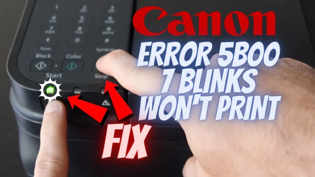
How to Fix Canon Error 5B00 Reset Not Working
When a software or manual reset for Canon Support Code 5B00 (waste ink absorber full counter) fails, the breakdown typically occurs at one of three levels: Service Mode entry failure, software-to-firmware handshake rejection (Service Tool Errors 006, 005, or 002), or a permanent EEPROM firmware lockout.
Under Canon’s architecture, the main logic board increments a hexadecimal counter inside an onboard non-volatile SPI/I2C EEPROM (such as a 24C16, 24C32, or 25Q-series IC) during printhead cleaning and initial ink charging cycles. When this counter reaches $100%$, firmware locks down all engine operations. If an incompatible or outdated version of the Canon Service Tool (such as running legacy ST v3400 on a newer G-series or TS-series printer) is executed, the firmware sets a permanent write-protection lock bit in the EEPROM. Once latched, the printer rejects software Service Mode commands and powers on with a solid orange error lamp during future service boot attempts.
Quick Diagnostic Matrix
| Symptom / Error Code | Underlying Root Cause | Diagnostic Check | Recommended Fix |
| Canon Service Tool returns “Error 006” | Printer is not in active Service Mode; Windows Print Spooler is locking the USB port | Check Power LED state (devmgmt.msc) | Kill spoolsv.exe; re-enter Service Mode until Power LED is solid green; plug into USB 2.0. |
| Canon Service Tool returns “Error 005” or “Error 002” | Service Tool version is incompatible with the printer’s generation, or functions are write-protected | Software Version Audit | Update to Service Tool v5103, v5306, or v5510; disable USB hubs. |
| Power LED turns solid Orange on Service Mode boot | Firmware Lockout: Previous failed reset attempt with an old tool permanently locked the EEPROM | Button Test (5 vs 6 presses) | Software reset is impossible. Re-flash or replace the onboard 8-pin EEPROM IC using a CH341A programmer. |
| Power LED flashes green continuously in Service Mode | Carriage stall or sensor flag stuck during initial service diagnostic self-test | Chassis Inspection | Clear carriage obstructions; ensure the top cover/scanner unit is completely closed. |
| WIC Reset / PrintHelp reports “Device Not Responding” | Printer connected via Wi-Fi; Service Mode disables all wireless network interfaces | Physical Cabling | Disconnect Wi-Fi; connect directly to a Windows PC via a USB-A to USB-B data cable. |
1. Verify Model-Specific Service Mode Entry Timing
The primary reason software resets fail with Error 006 is that the printer is in standard operating mode rather than diagnostic Service Mode. Different generations of Canon PIXMA and MAXIFY printers require different numbers of Stop button presses.
[Service Mode Button Timing Architecture]
 1. Printer is OFF, AC power cable connected.
 2. Press & HOLD [Stop] ──────────────────────────┐
 3. Press & HOLD [Power] ─────────────────────────┼── (Hold both for 2 seconds)
 4. RELEASE [Stop] (Keep [Power] held down!) ─────┘
 5. While holding [Power], press [Stop] N times:
      ├── 4 Times: Older MP / iP / early MG series
      ├── 5 Times: G1000, G2000, G3000, TS5000, TS6000, MG3600
      └── 6 Times: G1010, G2010, G3010, G4010, G5020, G6020, G7020
 6. RELEASE [Power].
 7. Wait 15–30 seconds ──► Power LED transitions from blinking green to SOLID GREEN.
Power off the printer. Ensure the AC cable is plugged directly into a wall outlet (bypass battery backups or surge strips that can create ground loops).
Connect the printer to a PC using a certified USB-A to USB-B cable. (Service Mode shuts down Wi-Fi transceivers completely; resetting over a wireless link will fail).
Press and hold down the Stop button (circle with an inverted triangle).
While holding Stop, press and hold the Power button.
Release the Stop button while continuing to hold the Power button down.
Press the Stop button:
Press 5 times: Standard for Canon G-series (G1000, G2000, G3000), PIXMA MG series, and TS series.
Press 6 times: Required on updated G-series revisions (G1010, G2010, G3010, G4010, G5020, G6020) and select MAXIFY models. If 5 presses results in an immediate amber light or fails to enumerate, use 6 presses.
Release the Power button.
Analyze the LED Behavior:
Solid Green: The printer is successfully in Service Mode. Windows will chime and detect a new peripheral (
CanonDeviceor a duplicated printer node in Device Manager). Proceed to Section 2.Solid Orange / Alternating Flash: The Service Mode firmware is hard-locked or the button sequence was mis-timed. Proceed to Section 4.
2. Eliminate Software Handshake Failures (Error 006, 005, 002)
If the printer is in Service Mode but the reset utility freezes or outputs numerical error codes when clicking Set, the software communication endpoint is colliding with Windows background services.
[System Diagnostic & Cleanup Sequence]
 ┌────────────────────────────────────────────────────────┐
 │ Windows Print Spooler (spoolsv.exe)                    │ <── Locks the USB pipe
 └──────────────────────────┬─────────────────────────────┘
                            │ Execute: net stop spooler
                            ▼
 ┌────────────────────────────────────────────────────────┐
 │ Purge Pending Print Queues: C:WindowsSystem32spool  │
 └──────────────────────────┬─────────────────────────────┘
                            │ Execute: net start spooler
                            ▼
 ┌────────────────────────────────────────────────────────┐
 │ Canon Service Tool (Run as Administrator)              │ ──► Sends EEPROM Zero-Byte
 └────────────────────────────────────────────────────────┘
Step A: Purge and Reset the Windows Print Spooler
A single paused or failed print job waiting in the Windows spooler locks the two-way USB communication channel (USB001), preventing the Service Tool from issuing low-level EEPROM write commands.
Press
Windows Key + S, typecmd, right-click Command Prompt, and select Run as administrator.Stop the spooler service:
DOSnet stop spoolerDelete all cached spooler print payloads:
DOSdel /Q /F /S "%systemroot%System32SpoolPrinters*.*"Restart the spooler service:
DOSnet start spooler
Step B: Match Service Tool Version to Printer Hardware Generation
Using an obsolete service utility version is a common cause of Error 005 and Error 002.
Service Tool v3400 / v3600: Designed strictly for older generation printers (MP280, MP250, iP2700). Never run v3400 on G-series or post-2015 models.
Service Tool v4905 / v5103: Compatible with Canon G1000, G2000, G3000, MG3500, MG3600 series.
Service Tool v5306 / v5510 / v5610: Required for Canon G1010, G2010, G3010, G4010, TS, and TR series printers.
[Canon Service Tool UI Operations]
 1. Launch compatible Service Tool (e.g., ST v5103) as Administrator.
 2. Under "Ink Absorber Counter":
      ├── Absorber: [Main] (or [All])
      ├── Counter Value (%): [0]
      └── Click [Set]
 3. Look for dialog response: "A function was finished."
 4. Under "Clear Ink Counter": Select [Main_Black / Main_Color] ──► Click [Set].
 5. Click [EEPROM] ──► Printer prints page showing "D=000.0%".
Step C: Bypass Port and Driver Conflicts
Disconnect all other USB devices (scanners, flash drives, additional printers) from your PC.
Plug the USB cable directly into a native USB 2.0 rear motherboard port (black port). Avoid blue USB 3.0/3.1 Gen 2 ports, front chassis headers, or unpowered hubs, which drop timing packets during EEPROM write operations.
Open Device Manager (
devmgmt.msc). Look under Universal Serial Bus controllers or Other devices. If the printer appears as an Unknown USB Device (Device Descriptor Request Failed), the USB cable is damaged or the USB-B port on the printer mainboard has broken solder traces.
3. Alternative Reset via WIC Reset Connect Utility
If the official Canon Service Tool continues to hang or report unhandled exceptions, the WIC Reset Utility bypasses standard Windows printer driver queues by writing directly to the USB hardware endpoint via its proprietary communication layer.
[WIC Reset Execution Path]
 USB Interface ──► WIC Reset Utility ──► Direct Endpoint Query ──► Clear Counter
Download and install WIC Reset Utility on a Windows or macOS system.
Place the printer into Service Mode (as detailed in Section 1) until the Power LED is solid green.
Connect the printer via USB and open WIC Reset.
Click Read Waste Counters:
If the software reads the counters (e.g., Main Waste Ink Counter: 100.2%), two-way communication is functional.
Click Reset Waste Counters.
When prompted, enter a purchased reset key (or use trial key
trialto reset the counter to $80%$ for immediate emergency functionality).Once the utility reports success, turn the printer off using the physical Power button, wait 15 seconds, and power it back on normally.
4. The Service Mode Hard Lockout (“Solid Orange LED”)
If your printer displays a solid orange/yellow LED immediately upon completing the Service Mode button sequence—and the Power LED never turns green—the mainboard is in a Hard Lockout state.
[EEPROM State Machine]
 Factory / Operating Mode ──► Boot with 5 Stop Presses ──► Service Mode (Solid Green)
                                                                 │
                                    [Outdated Service Tool Ran]  ▼
 Normal Mode (Error 5B00) ◄── EEPROM Security Bit Latched ◄── Lockout Byte Written
            │
            ▼
 [Subsequent Service Mode Boot Attempts Fail ──► SOLID ORANGE LED (No USB Comm)]
The Cause: When older Service Tool software (such as ST v2000, v3200, or unverified modified tools) attempts to communicate with modern Canon microcontrollers, it transmits an outdated command string into the memory controller. The internal security routine interprets this invalid write access as a hardware tamper event and writes a permanent lock-flag (
0xFFor invalid parity) to the configuration registers.The Reality: Once this lock-flag is written to the physical EEPROM chip, the microcontroller’s low-level boot code bypasses the Service Mode routine entirely. No software tool on earth can reset the printer via USB in this state.
The Solution: The EEPROM must be physically reprogrammed with a clean factory binary dump, replaced with a pre-programmed surface-mount IC, or the entire logic board must be swapped.
5. Hardware EEPROM Reprogramming via CH341A Programmer
When the logic board is locked in the solid orange state, recovering the machine requires re-flashing the 8-pin EEPROM IC (typically an SPI/I2C EEPROM from the 24Cxx or 25Qxx family) with a clean binary image extracted from a working donor printer.
[CH341A Programmer to Onboard EEPROM Interface]
 ┌────────────────────────────────────────────────────────┐
 │ Windows PC Running NeoProgrammer / AsProgrammer        │
 └──────────────────────────┬─────────────────────────────┘
                            │ USB Connection
                            ▼
 ┌────────────────────────────────────────────────────────┐
 │ CH341A USB Hardware Programmer (Set to 3.3V Mode!)     │
 └──────────────────────────┬─────────────────────────────┘
                            │ SOIC-8 Test Clip (Ribbon Cable)
                            ▼
 ┌────────────────────────────────────────────────────────┐
 │ Printer Main Logic Board                               │
 │                                                        │
 │             [ 8-Pin SOIC EEPROM IC ]                   │
 │             Pin 1 [•]           [ ] Pin 8 (VCC)        │
 │             Pin 2 [ ]           [ ] Pin 7 (WP)         │
 │             Pin 3 [ ]           [ ] Pin 6 (SCL)        │
 │             Pin 4 [ ]           [ ] Pin 5 (SDA)        │
 └────────────────────────────────────────────────────────┘
Step A: Locate the EEPROM IC on the Logic Board
Unplug all cables and disassemble the printer chassis to access the main logic board (QM7-series or QM4-series board).
Locate the surface-mount 8-pin SOIC chip:
G-Series (G1000/G2000/G3000): Marked
4G16,4G32(ATMEL/Microchip 24C16/24C32 equivalent) or25Q16/25Q32near the main ASIC controller.G-Series (G1010/G2010/G3010): Often features two ICs (an operational flash ROM and an EEPROM counter chip labeled
408RT/24C08).
Note the location of the Pin 1 indentation dot etched into the chip’s surface.
Step B: Connect the Hardware Programmer
Use an inexpensive CH341A USB Programmer equipped with an SOIC-8 test clip (allows in-circuit programming without desoldering).
Critical Voltage Check: Ensure your CH341A programmer is modified or configured for $3.3text{V}$ operation on the data lines (many unmodded black-PCB CH341A units output $5text{V}$, which can damage the printer’s primary processor).
Clamp the SOIC-8 test clip onto the pins of the target EEPROM, matching the red wire of the ribbon cable to Pin 1 of the chip.
Insert the programmer into a PC running NeoProgrammer or AsProgrammer.
Click Read IC (Detect). The software should identify the IC family (e.g.,
ATMEL AT24C16orWinbond W25Q16).
Step C: Flash the Clean Binary Payload
Back Up Current Firmware: Click Read, then click Save to write the current corrupted/locked EEPROM contents to a
.binfile on your PC.Load Donor Firmware: Download a verified clean
.binEEPROM dump matching your specific printer model and motherboard revision (available across technician repositories like Badcaps, TestCopy, or 2manuals).Open the clean
.binfile in the programming software.Click Erase IC, then click Write (Program).
Click Verify to compare the flash contents byte-by-byte with the source file.
Remove the test clip, reassemble the printer, and power it on. The counter will be restored to $0.0%$, the lockout bit will be removed, and the printer will boot into a normal operational ready state.
6. Logic Board Replacement (Drop-In Hardware Fix)
If you do not possess micro-soldering or EEPROM programming tools, replacing the mainboard is the standard field service remedy for a solid-orange lockout state.
[Mainboard Replacement Procedure]
 1. Disconnect all FFC (Flat Flexible Ribbon) cables with an ESD-safe pull.
 2. Remove 4x Phillips mounting screws.
 3. Verify OEM Part Number on Silkscreen (e.g., QM7-4570 for G2000; QM7-5452 for G2010).
 4. Drop in new board; transfer carriage and sensor connectors.
 5. Power on ──► Run Head Alignment calibration.
Part Number Matching: Never purchase a board based on model name alone. Check the physical silkscreen white-ink label printed directly on the PCB (e.g.,
QM7-4570-000orQM4-4428-000). Installing a board with an incompatible revision will trigger carriage indexing faults.Cost Analysis: OEM replacement mainboards for high-volume models (such as the Canon G-series) generally cost between $15 and $25, making them a cost-effective alternative to discarding the printer.
7. Physical Ink Absorber Maintenance Reminder
Clearing Support Code 5B00—via software reset, EEPROM flashing, or board replacement—only resets the digital counter. It does not remove the physical waste ink resting inside the bottom floor of the printer.
[Chassis Base Fluid Dynamics]
 ┌────────────────────────────────────────────────────────┐
 │ Main Logic Board (Freshly Reset Counter = 0.0%)        │
 ├────────────────────────────────────────────────────────┤
 │ Porous Felt Absorber Sponges (PHYSICALLY 100% FULL)    │ <── Conductive liquid ink
 └──────────────────────────┬─────────────────────────────┘     will overflow!
                            ▼
              [Desk Damage / Board Short Risk]
If the 5B00 error triggered naturally through months or years of heavy use, the porous felt pads in the base of the machine are fully saturated with glycol-based ink. If left unserviced:
Liquid ink will seep through the bottom seams of the plastic chassis, permanently staining desks and floors.
During transport or tilting, ink can splash onto the power supply unit or mainboard traces, causing a catastrophic electrical short.
Always remove the lower casing to wash and dry the felt sponges, or cut the peristaltic pump’s clear silicone discharge tube and extend it out through a small hole in the rear plastic housing into an external waste ink reservoir bottle.
If your printer continues to flash amber/orange after a successful EEPROM flash, or if the Power LED will not hold a steady green state in Service Mode despite using a verified USB 2.0 connection and a compatible Service Tool, the problem has shifted beyond counter saturation. This indicates a physical hardware failure on the logic board, such as a blown power regulator diode, a burnt peristaltic purge motor driver IC, or an open-circuit failure on the carriage optical encoder sensor rail, which requires circuit-level component testing or a complete mainboard swap.