
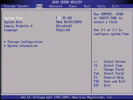
How to Fix NVMe SSD Not Recognized in BIOS After an Update
When a motherboard BIOS or firmware update causes an NVMe M.2 SSD to disappear from the UEFI hardware tree, the flashing process has typically reset system NVRAM to factory defaults, re-enabled Intel VMD/RAID controller encapsulation, altered PCIe lane bifurcation, or toggled legacy CSM boot states. Because NVMe drives rely on direct high-speed PCIe lane negotiation and native UEFI Option ROMs, an updated firmware build will fail to poll the drive if pre-boot storage parameters and power states are misaligned.
Quick Diagnostic Matrix
| Symptom | Root Cause | Setting / Path | Recommended Fix |
| Drive missing from boot list on Intel 11th–14th Gen boards | BIOS update restored default Intel VMD, routing NVMe endpoints behind a virtual RAID controller | BIOS > Advanced > VMD Configuration | Set Enable VMD Controller to Disabled to expose raw PCIe endpoints. |
| SSD absent from both Boot Order and NVMe Configuration | UEFI switched to Legacy/CSM or Fast Boot skipped electrical PCIe link training | BIOS > Boot > CSM Support | Disable CSM, enforce UEFI Only, and toggle Fast Boot to Disabled. |
| Secondary/chipset M.2 drive vanished after flash | M.2 slot operating mode reverted to SATA or Auto with lane-sharing conflicts | BIOS > Advanced > Onboard Devices | Manually lock M.2 slot mode to PCIe / NVMe (avoid Auto) and check SATA ports. |
| System boots directly into BIOS setup on every start | Stale NVRAM boot pointers conflict with existing EFI System Partition (ESP) | Motherboard CLR_CMOS / Battery | Clear CMOS jumper pins to flush out-of-sync NVRAM device descriptors. |
1. Disable Intel VMD / Intel RST (Intel Motherboards)
On Intel motherboards (Z490 through Z790, B660, B760), flashing a new BIOS version almost always resets Intel VMD (Volume Management Device) to “Enabled.” VMD aggregates NVMe storage under an enterprise RAID controller. When active without pre-configured RAID volumes, the BIOS completely hides the raw NVMe SSD from standard boot lists and the UEFI NVMe Device tree.
- Power on your PC and tap
DelorF2to enter the UEFI BIOS. - Press
F7to enter Advanced Mode. - Navigate to System Agent (SA) Configuration > VMD Configuration (or Advanced > Storage Configuration).
- Locate Enable VMD Controller (or Intel Rapid Storage Technology) and change it to Disabled.
- Locate any sub-settings such as Map PCIE Storage Under VMD and ensure they are disabled.
- Press
F10to save changes and restart. The drive will immediately register under the standard UEFI storage tree.
[UEFI BIOS (Advanced Mode)]
 └── Advanced (or System Agent Configuration)
      └── VMD Configuration
           └── Enable VMD Controller > [Set to DISABLED]
2. Enforce Pure UEFI Boot and Disable CSM
NVMe solid-state drives cannot boot using legacy Master Boot Record (MBR) interrupts; they require the native UEFI driver stack. If a firmware update enables the Compatibility Support Module (CSM) or sets storage execution policies to “Legacy,” the BIOS will not initialize the NVMe Option ROM during POST.
- In the BIOS menu, switch to the Boot tab.
- Locate CSM (Compatibility Support Module) or Launch CSM.
- Set CSM to Disabled.
- If your motherboard requires CSM for other devices, scroll down to Storage OpROM Policy (or Boot Device Control) and force it strictly to UEFI Only.
- Navigate to the Security or Boot tab, locate OS Type, and verify it is set to Windows UEFI Mode rather than Other OS.
- Save and exit (
F10).
3. Clear CMOS to Flush Stale NVRAM Mapping
Flashing new microcode updates the read-only SPI flash chip, but the motherboard’s operational device mappings are held in battery-backed volatile NVRAM. If the updated BIOS tries to parse old hardware indices (
Boot0001, Boot0002) that were cached by the previous firmware version, the board drops the PCIe slot handshake.[Disconnect AC Wall Power]
└── Hold PC Power Button for 15 Seconds (Drain residual energy)
└── Short CLR_CMOS / JBAT1 pins with metal screwdriver for 10–15 Seconds
└── (Or remove CR2032 coin cell for 10 minutes)
- Switch off the power supply unit (PSU) and disconnect the AC power cord from the wall.
- Press and hold the computer’s front power button for 15 seconds to discharge all power from motherboard capacitors.
- Locate the Clear CMOS pins (labeled
JBAT1,CLR_CMOS, orRESET_BIOSnear the bottom of the board or next to the battery). - Bridge the two pins with a metal screwdriver or jumper block for 10 to 15 seconds.
- Alternatively, gently pop out the silver CR2032 coin-cell battery for 10 minutes, then reinsert it.
- Reconnect power and boot into BIOS. The firmware will rebuild clean hardware tables and re-scan the PCIe bus.
4. Reconfigure M.2 Slot Operating Mode and PCIe Bifurcation
BIOS updates often alter onboard chipset multiplexing. If your NVMe SSD is seated in a secondary slot that shares high-speed I/O (HSIO) lanes with physical SATA ports or secondary PCIe slots, the default “Auto” detection setting can fail.
- Inside BIOS Advanced Mode, navigate to Advanced > Onboard Devices Configuration.
- Locate the setting for your specific M.2 slot (e.g.,
M.2_2 ConfigurationorPCIeX16_2 Bandwidth). - If the slot mode is set to Auto or SATA Mode, manually lock it to PCIe Mode (or NVMe Mode).
- If the slot allows link speed selection, change it from Auto to Gen 3 or Gen 4 (matching your SSD’s native spec) to prevent signal attenuation errors during the initial link speed negotiation.
- If you are using a PCIe-to-M.2 riser card, find PCIe Bifurcation and set the slot from
x16toPCIE 4x4orx4/x4/x4/x4.
5. Disable Fast Boot to Force Complete PCIe Link Training
“Fast Boot” speeds up boot times by bypassing comprehensive hardware link training and reusing previously cached device states. Following a BIOS update, the PCIe Physical Layer (PHY) clock baselines often shift; if Fast Boot is enabled, the board will time out before the SSD controller completes its low-voltage electrical handshake.
- Navigate to the Boot tab in your BIOS.
- Locate Fast Boot.
- Toggle it to Disabled.
- In the same menu, look for POST Delay Time (or Setup Prompt Timeout) and set it to 3 seconds or 5 seconds. This gives slower NVMe controllers (especially high-capacity DRAM-less drives) sufficient time to stabilize power rails before the motherboard completes POST.
6. Perform a Cold Hardware Discharge and Reseat
SSD controller chips (such as those from Phison, Silicon Motion, or Samsung) run their own microcode. During automated reboots triggered by a BIOS flash utility, the SSD controller can hang in an undefined sleep state (D3hot/D3cold) while the motherboard re-initializes.
- Shut down the computer completely and unplug the power cable.
- Remove the M.2 SSD from its slot.
- Inspect the gold contact pins for dust or thermal pad oil residue; wipe clean with a dry microfiber cloth if necessary.
- If your drive was in a chipset-routed slot (lower half of the motherboard), move it to the primary CPU-attached M.2 slot (
M.2_1, located directly between the CPU socket and top PCIe x16 GPU slot). Primary slots communicate directly with the processor’s PCIe lanes, bypassing secondary chipset initialization bugs. - Insert the SSD at a 30-degree angle, secure the standoff screw until snug, reconnect power, and boot straight into the BIOS.
If the NVMe SSD refuses to register after verifying VMD settings, clearing CMOS, and disabling CSM, the updated BIOS version may contain an AGESA (AMD) or microcode (Intel) bug that drops compatibility with your drive’s controller firmware. In that case, download the previous stable BIOS version from your motherboard manufacturer’s website, load it onto a FAT32 USB drive, and roll back the firmware using your board’s dedicated hardware flashing port (BIOS Flashback / Q-Flash Plus).