
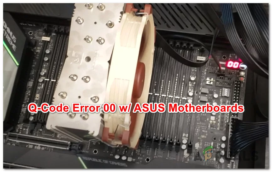
How to Fix ASUS Motherboard Q-Code 00 (No Display)
On ASUS motherboards equipped with a 2-digit diagnostic LED display (ROG Maximus, ROG Crosshair, ProArt, and select Strix models), Q-Code “00” designates that the CPU has failed to initialize or execute its initial reset vector ($CPURST#$). Unlike later POST codes that indicate memory training halts (e.g., Code 55) or peripheral handshake stalls (e.g., Code 99), Code 00 occurs before the Power-On Self-Test sequence begins.
When the board displays Code 00 with a black screen, the processor’s primary voltage rail is unpowered, the motherboard’s Power Good ($PWRGD$) logic circuit is open, the BIOS microcode is corrupted or incompatible with the installed processor generation, uneven cooler mounting pressure has lifted pins off the socket grid array, or the CPU or motherboard VRM has suffered hardware failure.
Quick Diagnostic Matrix
| Symptom / Behavior | Root Cause | Inspection / Tool | Recommended Fix |
| Code 00 instantly upon pressing power; fans spin at 100% | EPS12V CPU 8-pin cable unplugged, loose, or PCIe cable plugged in by error | Upper-left Motherboard Edge | Connect dedicated 8-pin EPS/CPU power cables (do not use 8-pin PCIe cables). |
| Code 00 on a brand-new motherboard or after a CPU upgrade | Outdated BIOS firmware lacking microcode for the installed CPU generation | Rear I/O Panel (FlashBack) | Flash the latest UEFI BIOS using the ASUS USB BIOS FlashBack button. |
| Code 00 after installing/reseating CPU cooler or contact frame | Uneven or excessive mounting torque warping the socket/substrate | Screwdriver / Socket Tension | Loosen cooler screws half a turn; check for bent pins in the LGA socket. |
| System clicks off immediately after showing Code 00 | Direct short-to-ground on 12V CPU rail or chassis standoff misplaced | Power Supply (OCP) | Bench-test motherboard outside the PC chassis (breadboard test). |
| Code 00 appeared randomly after stable operation | Corrupted CMOS state tables, dead CR2032 battery, or degraded CPU/VRM | Clear CMOS Button / Multimeter | Clear CMOS; drain flea power; replace CR2032 battery ($>3.0text{V}$). |
1. Verify EPS12V CPU Power Cabling (Avoid the PCIe Cable Hazard)
The most common cause of Code 00 during initial assembly or power supply swaps is a missing, loose, or incorrectly keyed CPU power cable at the top-left edge of the motherboard.
[Motherboard Top-Left Corner]
 ┌────────────────────────────────────────────────────────┐
 │ [EPS_12V_1 (8-Pin)]     [EPS_12V_2 (4/8-Pin)]          │
 │ ┌──┬──┬──┬──┐           ┌──┬──┬──┬──┐                  │
 │ │12│12│12│12│           │12│12│12│12│  <── Must be EPS/CPU Cables!
 │ ├──┼──┼──┼──┤           ├──┼──┼──┼──┤      (NOT PCIe Graphics Cables)
 │ │G │G │G │G │           │G │G │G │G │                  │
 │ └──┴──┴──┴──┘           └──┴──┴──┴──┘                  │
 └────────────────────────────────────────────────────────┘
The PCIe vs. EPS Cable Mistake: Never plug an 8-pin PCIe auxiliary cable (intended for graphics cards) into the motherboard’s 8-pin CPU power socket. While both are 8-pin connectors, their pinouts and plastic keying are fundamentally different:
EPS12V (CPU): Top 4 pins are $+12text{V}$; bottom 4 pins are Ground.
PCIe (GPU): Top 3 pins are $+12text{V}$; bottom 5 pins are Ground/Sense.
Forcing a PCIe cable into the EPS header creates a direct $+12text{V}$-to-Ground short circuit, which immediately trips the power supply’s Over-Current Protection (OCP) and halts the board at Code 00.
Dual Cable Requirements: On high-end ASUS ROG boards, connect both the primary 8-pin (
CPU_PWR1) and the secondary 4/8-pin (CPU_PWR2) connectors to ensure proper voltage delivery across high-draw processors.Modular PSU End: Check the power supply unit itself. Ensure the modular cable is plugged into the port labeled CPU, not PCIe/VGA.
2. Flash BIOS via ASUS USB BIOS FlashBack
If you install a newer generation CPU on an older motherboard chipset (e.g., an Intel 14th Gen CPU on a Z690/Z790 board, or an AMD Ryzen 9000/7000X3D series on an X670/B650 board), the motherboard’s factory-installed BIOS will lack the microcode required to identify the processor’s core topology. The board halts at Code 00 before initializing the display.
You can flash the BIOS without a display, RAM, or a working CPU using ASUS USB BIOS FlashBack.
[ASUS Rear I/O Panel]
 ┌──────────────────────────────────────────────┐
 │ [USB Ports]   [BIOS FlashBack Button] (LED)  │
 │ ┌─────────┐   ┌───────┐                      │
 │ │ BIOS USB│   │ ( o ) │ ◄── Dedicated Button │
 │ └─────────┘   └───────┘                      │
 └──────────────────────────────────────────────┘
On a secondary computer, download the latest stable UEFI BIOS for your exact motherboard model from the official ASUS Support page.
Extract the downloaded
.zipfile.Run the included executable named
BIOSRenamer.exe:Mechanism: The utility automatically renames the raw BIOS binary to the specific shortened string required by the board’s hardware FlashBack IC (e.g.,
M13H.CAP,C8F.CAP, orTGX670E.CAP).
Prepare a USB flash drive:
Format the USB drive to FAT32 with an MBR (Master Boot Record) partition table (drives larger than 32 GB formatted to exFAT or GPT will fail to initialize).
Copy the renamed
.CAPfile directly to the root directory of the USB drive (do not place it inside folders).With the target PC powered OFF (power supply switched on, standby lights illuminated on the motherboard):
Insert the USB drive into the specific rear USB port outlined with a white or silver border labeled BIOS or FlashBack.
Press and hold the rear BIOS FlashBack button for 3 seconds until the indicator LED begins blinking.
Release the button.
Flashing in Progress: The LED will blink slowly, then accelerate as the payload writes to the SPI flash ROM (takes roughly 3 to 6 minutes).
Flash Complete: The LED will turn off completely.
Flash Failed: If the LED remains solid, blinks 5 times and stops, the flash drive is not formatted to FAT32 MBR, the port was wrong, or the
.CAPfile was not renamed properly.
3. Clear CMOS & Perform a Cold Flea-Power Drain
Corrupted register parameters inside non-volatile CMOS memory can leave the memory controller or voltage regulators locked in an invalid state.
[Cold Power Drain Workflow]
 1. Switch off PSU rocker switch (O) & pull AC Power Cable from the wall.
 2. Remove the CR2032 Coin Cell Battery from the motherboard.
 3. Press and hold the Chassis Power Button + Rear "Clear CMOS" button for 30 Seconds.
 4. Leave completely unpowered for 10 Full Minutes.
 5. Reinsert CR2032 Battery (Verify > 3.0V with Multimeter) ──► Boot System.
Turn off the PSU and disconnect the AC power cord from the wall outlet.
Locate the Clear CMOS button on the rear I/O shield (or bridge the two-pin
CLRTCheader on the lower motherboard edge using a flat-head screwdriver for 10 seconds).Remove the CR2032 coin-cell battery. If the battery voltage has dropped below $2.8text{V}$, the motherboard can fail cold-boot state initialization; test the cell with a multimeter or replace it with a fresh battery.
Press and hold the physical power button on the PC chassis for 30 seconds to bleed residual voltage stored inside the motherboard’s VRM capacitors.
Reinstall the battery, reconnect the AC power cord, and power on the system. Allow up to 2 minutes for initial memory and hardware re-training.
4. Check Cooler Mounting Pressure & Inspect Socket Pins
On modern high-density sockets (Intel LGA 1700 / LGA 1851 and AMD AM5), the pins inside the socket act as flexible leaf springs. If a CPU cooler is mounted unevenly or torqued down with excessive force, the motherboard PCB flexes. This lifts microscopic pins away from the processor’s bottom gold contact pads ($V_{CC}$ power delivery, ground, or clock traces), locking the CPU in a reset loop at Code 00.
[LGA Socket Pin Contact Array]
 ┌────────────────────────────────────────────────────────┐
 │ CPU Substrate (PCB)                                    │
 │ ░░░░░░░░░░░░░░░░░░░░░░░░░░░░░░░░░░░░░░░░░░░░░░░░░░░░░ │
 │   [Pad]   [Pad]   [Pad]   [Pad]   [Pad]   [Pad]   [Pad]│
 └─────┼───────┼───────┼───────┼───────┼───────┼───────┼──┘
       │       │       │       ▲
       ▼       ▼       ▼       │
   [ Pin ] [ Pin ] [ Pin ]  [ Bent Pin / Lost Contact ] ──► CODE 00
 ┌────────────────────────────────────────────────────────┐
 │ Motherboard LGA Socket Base                            │
 └────────────────────────────────────────────────────────┘
Loosen Cooler Mounting Tension:
Back off each retaining screw on the CPU cooler bracket by half a turn to one full turn.
If using an aftermarket aftermarket anti-bending contact frame (such as Thermalright or Thermal Grizzly on LGA 1700), ensure the four retaining screws were tightened only until initial resistance in a criss-cross pattern. Over-torquing contact frames directly causes Code 00.
Inspect the Physical Socket for Bent Pins:
Unmount the cooler, open the socket retention arm, and remove the processor.
Use a bright flashlight and a smartphone camera with macro zoom to inspect the socket pin array from multiple angles.
Look for irregular reflections across the pin grid. A single pin bent out of alignment, broken off, or caked with non-conductive thermal paste residue will prevent the CPU from asserting $PWRGD$.
AM4 Processors: If using an older PGA socket, inspect the underside of the processor itself to verify no pins are bent, broken, or contaminated with thermal compound.
Re-seat the Processor:
Re-seat the CPU strictly aligned with its orientation triangles/notches. Lock the retention arm down and re-mount the cooler using even, alternating diagonal turns.
5. Bench-Test the Motherboard (Eliminate Standoff Shorts)
An unexpected electrical ground short between the back of the motherboard and the metal chassis will force the power supply to cut voltage to the motherboard’s sensitive low-voltage logic planes.
[Breadboard / Out-of-Chassis Test Setup]
 ┌────────────────────────────────────────────────────────┐
 │ Motherboard placed on its Non-Conductive Packaging Box │
 │                                                        │
 │ ├── [CPU + Cooler Connected]                           │
 │ ├── [1x RAM Stick in Slot A2]                          │
 │ ├── [24-Pin ATX + 8-Pin EPS CPU Power Connected]       │
 │ └── [NO GPU, NO SSD, NO CHASSIS WIRES]                 │
 └────────────────────────────────────────────────────────┘
Disconnect all external peripherals, front-panel headers (power switch, reset switch, USB, HD Audio), and SATA drives.
Remove the motherboard from the computer case.
Place the motherboard on a non-conductive surface, such as its original cardboard packaging box (never place it on the static-shielding bag, which has a mildly conductive exterior coating).
Remove all expansion cards (GPUs, sound cards, capture cards) and remove all M.2 NVMe SSDs.
Install only:
The CPU and CPU cooler (fan connected to
CPU_FAN).A single stick of RAM seated firmly in primary slot A2 (second slot from CPU).
The 24-pin ATX main power cable and the 8-pin EPS CPU power cable.
Power on the system using the onboard Start / Power button on the ASUS motherboard PCB (or momentarily bridge the two
PWR_SWfront panel pins with a flat screwdriver).Observe the Q-Code display:
If the code advances beyond 00 (e.g., stops at Code 53, 55, or progresses toward C1/dE): A metal case standoff was shorting the back of the board, the rear I/O shield grounding tabs were wedged inside a USB port, or a peripheral/riser cable was shorted.
If the code remains locked at 00: Proceed to Section 6.
6. CPU vs. Motherboard VRM Hardware Failure Isolation
If the power cables are verified, the BIOS has been updated via FlashBack, the socket pins are undamaged, and the board still shows Code 00 on an open bench test, the fault is isolated to physical hardware failure in either the CPU or the motherboard power delivery system.
[ASUS Onboard Q-LED Diagnostic Strip]
 ┌────────────────────────────────────────────────────────┐
 │ [BOOT] (Yellow-Green)                                  │
 │ [VGA ] (White)                                         │
 │ [DRAM] (Yellow)                                        │
 │ [CPU ] (Red) ◄── [STUCK SOLID RED ALONGSIDE CODE 00]   │
 └────────────────────────────────────────────────────────┘
Inspect the Onboard Q-LEDs: Look directly adjacent to the 24-pin power connector or the Q-Code display. If Code 00 is accompanied by a solid RED CPU LED, the motherboard’s monitoring circuitry confirms that the CPU has failed its internal health check or the VRM controller cannot establish voltage regulation across the $V_{CORE}$ or $V_{CCIN}$ rails.
Inspect the Motherboard VRM Stages: Examine the capacitors and MOSFET power stages flanking the CPU socket under the aluminum heatsinks. Look for:
Discolored, blackened, or burnt power stages.
A distinct electrical burning odor near the VRM chokes.
Blown surface-mount bypass capacitors on the bottom or top layers of the board.
Component Isolation (The Final Test):
Because Code 00 means the CPU and board are not communicating, software diagnostics cannot run.
Testing requires swapping one known-working component: either test the CPU in an alternate compatible motherboard, or install an inexpensive, compatible donor CPU into the current ASUS motherboard.
If a known-working processor also displays Code 00, the motherboard’s chipset, socket, or primary VRM driver IC has failed. If the donor processor boots normally, the original CPU has suffered internal silicon degradation or an open-circuit failure on its internal power plane.
If your ASUS motherboard remains locked on Q-Code 00 after a successful USB BIOS FlashBack update, verification of dedicated EPS12V power cables, socket pin inspection, and an out-of-chassis breadboard run, the failure is a physical hardware defect. This indicates that either the processor has suffered internal electrical breakdown (such as a dead internal power-management controller or memory bus short) or the motherboard’s Voltage Regulator Module (VRM) has suffered a blown high-side MOSFET that prevents the board from asserting the hardware $PWRGD$ signal. Resolving this requires filing an RMA or replacing the damaged CPU or motherboard.